LTC4066/LTC4066-1
1
4066fc
TYPICAL APPLICATION
FEATURES
APPLICATIONS
DESCRIPTION
USB Power Controller and
Li-Ion Linear Charger with
Low Loss Ideal Diode
The LTC
®
4066/LTC4066-1 are USB power managers and
Li-Ion battery chargers designed to work in portable
battery-powered applications. The parts control the total
current used by the USB peripheral for operation and
battery charging. The total input current can be limited
to 100mA, 500mA or “unlimited” (i.e., above 2A). Battery
charge current is automatically reduced such that the sum
of the load current and the charge current does not exceed
the programmed input current limit.
The LTC4066/LTC4066-1 include a standalone constant-
current/constant-voltage linear charger for single cell
Li-ion batteries. The fl oat voltage applied to the battery
is held to a tight 0.8% tolerance, and charge current
is programmable using an external resistor to ground.
A programmable end-of-charge status output (CHRG)
indicates full charge. BAT pin charge and discharge cur-
rents can be monitored via an analog output (I
STAT
). Total
charge time is programmable by an external capacitor to
ground. When the battery drops 100mV below the fl oat
voltage, automatic recharging of the battery occurs. Also
featured is an NTC thermistor input used to monitor bat-
tery temperature while charging.
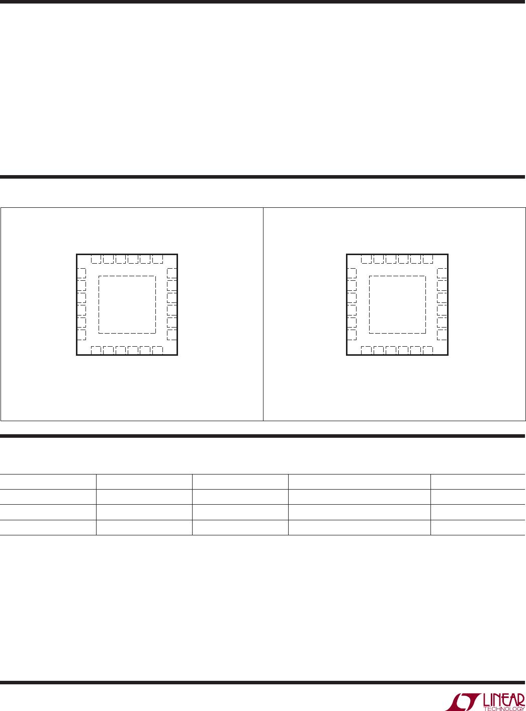
The LTC4066/LTC4066-1 are available in a 24-pin thin
profi le (0.75mm) 4mm × 4mm QFN package. The LTC4066
is also available in a 24-pin ultrathin profi le (0.55mm)
4mm × 4mm UTQFN package.
n
Portable USB Devices
n
GPS, Cameras, Broadband Wireless Modems
n
Mulitple Input Chargers
L, LT, LTC and LTM are registered trademarks of Linear Technology Corporation. PowerPath
is a trademark of Linear Technology Corporation. All other trademarks are the property of their
respective owners. *Protected by U.S. Patents including 6522118.
n
Seamless Transition Between Input Power Sources:
Li-Ion Battery, USB and 5V Wall Adapter
n
Low Loss (50mΩ) Ideal Diode Path from BAT to OUT
n
Programmable Charge Current Detection (CHRG)
n
Load Dependent Charging Guarantees USB Input
Current Compliance
n
Analog Gas Gauge Function
n
Charges Single Cell Li-Ion Batteries Directly from
USB Port
n
Constant-Current/Constant-Voltage Operation with
Thermal Feedback to Maximize Charging Rate
Without Risk of Overheating*
n
Selectable 100% or 20% Current Limit
(e.g., 500mA/100mA)
n
Termination Timer Adapts to Actual Charge Current
n
Preset 4.2V Charge Voltage with 0.8% Accuracy
(4.1V for LTC4066-1)
n
NTC Thermistor Input for Temperature Qualifi ed
Charging
n
Thin Profi le (0.75mm) 24-Lead 4mm × 4mm
QFN Package
n
Ultrathin Profi le (0.55mm) 24-Lead 4mm × 4mm
UTQFN Package (LTC4066 Only)
+
IN
V
NTC
NTC
WALL
SHDN
SUSP
HPWR
CLDIS
OUT
4.7μF
510Ω
TO ADC FOR
GAS GAUGE
510Ω
4.7μF
TIMER PROG
LTC4066
CLPROG GND
4066 TA01
TO LDOs,
REGs, ETC
BAT
CHRG
ACPR
POL
I
STAT
0.1μF 100k 2k
SUSPEND USB POWER
500mA/100mA SELECT
5V (NOM)
FROM USB
CABLE V
BUS
2k
INPUT CURRENT
LIMIT DISABLE
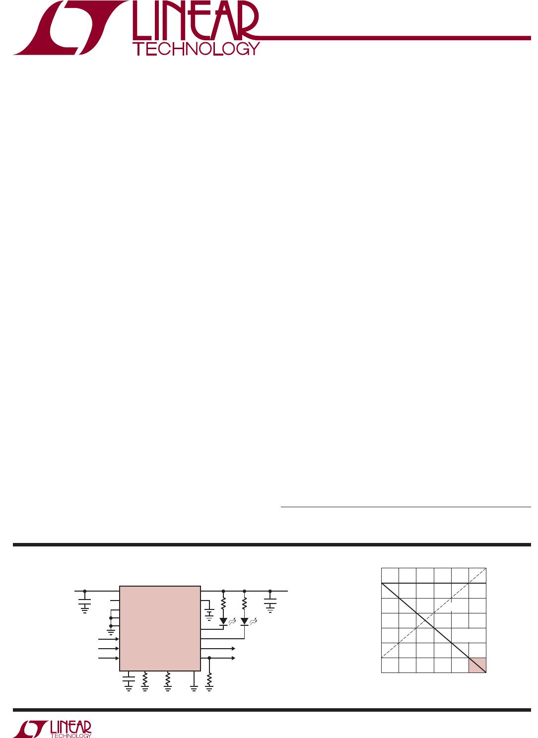
I
LOAD
(mA)
0
CURRENT (mA)
300
400
600
500
I
IN
400
4066 TA02
200
100
–100
0
100
200
300
600500
I
BAT
CHARGING
I
LOAD
I
BAT
(IDEAL DIODE)