LTC4066/LTC4066-1
12
4066fc
OPERATION
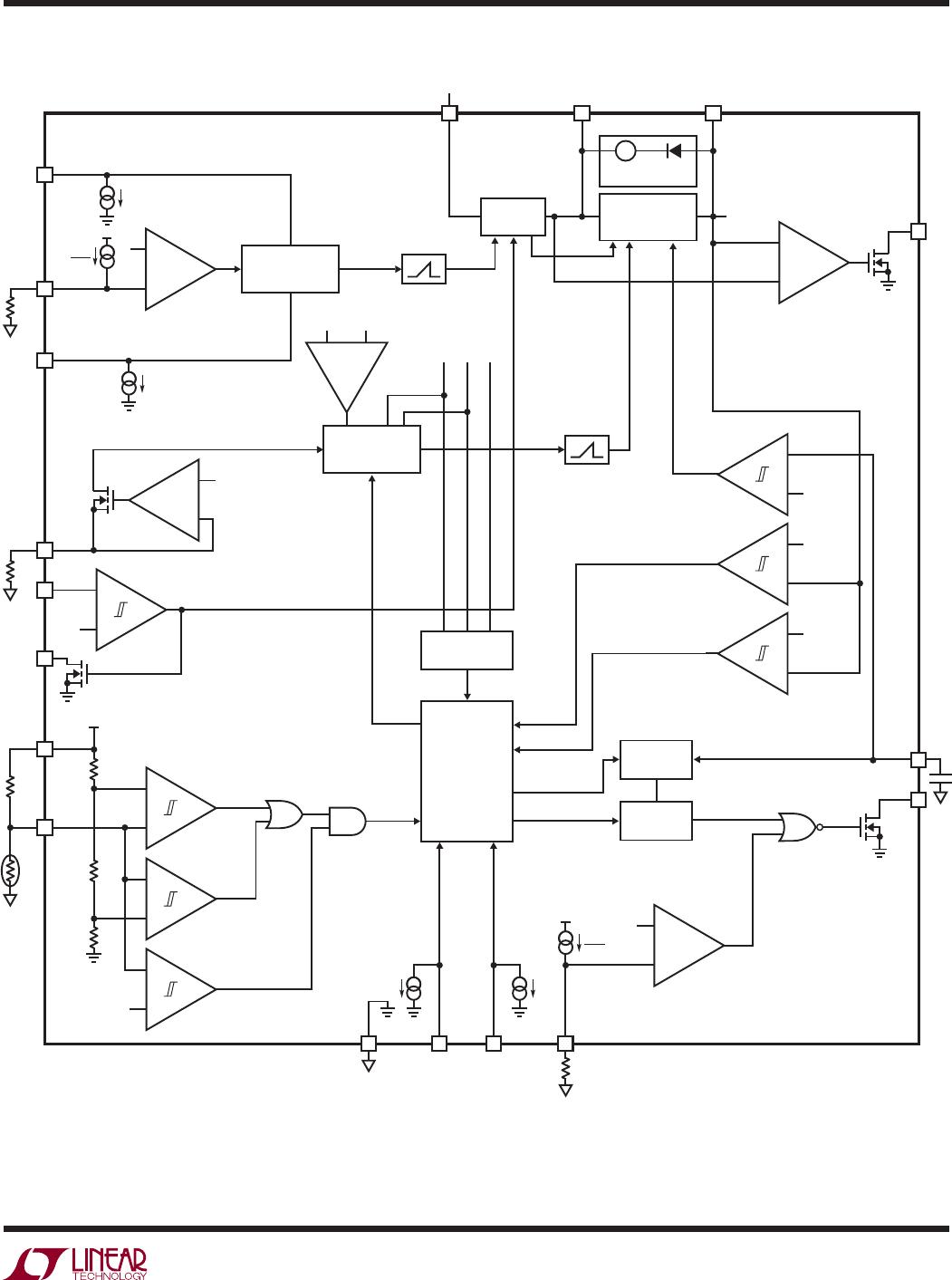
The LTC4066/LTC4066-1 are complete PowerPath
TM
controllers for battery-powered USB applications. The
LTC4066/LTC4066-1 are designed to receive power from a
USB source, a wall adapter or a battery. It can then deliver
power to an application connected to the OUT pin and a
battery connected to the BAT pin (assuming that an external
supply other than the battery is present). Power supplies
that have limited current resources (such as USB V
BUS
supplies) should be connected to the IN pin which has a
programmable current limit. Battery charge current will
be adjusted to ensure that the sum of the charge current
and load current does not exceed the programmed input
current limit.
An ideal diode function provides power from the battery
when output/load current exceeds the input current limit or
when input power is removed. Powering the load through
the ideal diode instead of connecting the load directly to
the battery allows a fully charged battery to remain fully
charged until external power is removed. Once external
power is removed, the output drops until the ideal diode
is forward biased. The forward biased ideal diode will then
provide the output power to the load from the battery.
Furthermore, powering switching regulator loads from the
OUT pin (rather than directly from the battery), results in
shorter battery charge times. This is due to the fact that
switching regulators typically require constant input power.
When this power is drawn from the OUT pin voltage (rather
than the lower BAT pin voltage) the current consumed
by the switching regulator is lower, leaving more current
available to charge the battery.
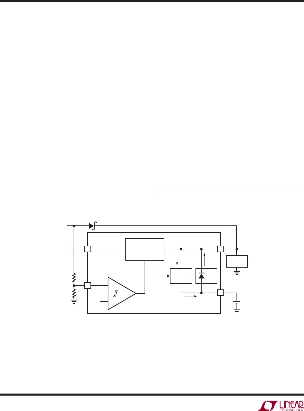
The LTC4066/LTC4066-1 also have the ability to receive
power from a wall adapter. Wall adapter power can be con-
nected to the output (load side) of the LTC4066/LTC4066-1
through an external device such as a power Schottky or
FET, as shown in Figure 1. The LTC4066/LTC4066-1 have
the unique ability to use the output, which is powered
by the wall adapter, as a path to charge the battery while
providing power to the load. A wall adapter comparator
on the LTC4066/LTC4066-1 can be confi gured to detect
the presence of the wall adapter and shut off the connec-
tion to the USB to prevent reverse conduction out to the
USB bus.
PowerPath is a trademark of Linear Technology Corporation.
–
+
+
20
WALL
1.25V
9
IN
USB V
BUS
WALL
ADAPTER
OUT
1,3,8
2,4,5
BAT
4066 F01
CURRENT LIMIT
CONTROL
ENABLE
CHRG
CONTROL
IDEAL
DIODE
Li-Ion
LOAD
Figure 1. Simplifi ed Block Diagram—PowerPath