LTC4066/LTC4066-1
4
4066fc
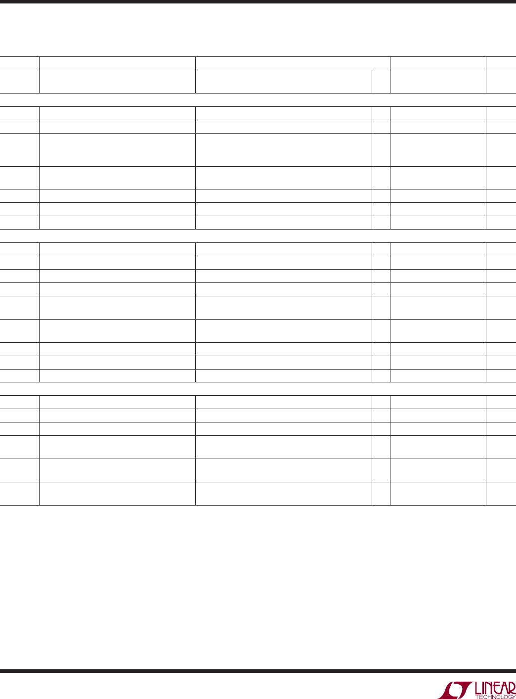
ELECTRICAL CHARACTERISTICS
The l denotes the specifi cations which apply over the full operating
temperature range, otherwise specifi cations are at T
A
= 25°C. V
IN
= 5V, V
BAT
= 3.7V, HPWR = 5V, WALL = 0V, R
PROG
= 100k,
R
CLPROG
= R
ISTAT
= 2k, unless otherwise noted.
SYMBOL PARAMETER CONDITIONS MIN TYP MAX UNITS
T
LIM
Junction Temperature in Constant
Temperature Mode
105 °C
Ideal Diode
R
FWD
Incremental Resistance, V
ON
Regulation I
BAT
= 500mA 27
R
DIO(ON)
On-Resistance V
BAT
to V
OUT
I
BAT
= 3A 45
V
FWD
Voltage Forward Drop (V
BAT
– V
OUT
)I
BAT
= 5mA
I
BAT
= 200mA
I
BAT
= 2A
l
10 30
47
95
50 mV
mV
mV
k
DIO,ISTAT
Ratio of I
BAT
(Discharging Through Ideal
Diode) to I
STAT
Pin Current
I
BAT
= 5mA
I
BAT
= 20mA
850
850
1000
1000
1150
1150
mA/mA
mA/mA
V
OFF
Diode Disable Battery Voltage 2.8 V
I
FWD
Load Current Limit for V
ON
Regulation V
BAT
= 3.5V 2.5 A
I
D(MAX)
Diode Current Limit 3.8 5.2 A
Logic
V
OL
Output Low Voltage (CHRG, ACPR, POL) I
SINK
= 5mA
l
0.1 0.25 V
V
IH
Enable Input High Voltage SUSP, SHDN, HPWR, CLDIS Pin
l
1.2 V
V
IL
Enable Input Low Voltage SUSP, SHDN, HPWR, CLDIS Pin
l
0.4 V
I
PULLDN
Logic Input Pull-Down Current SUSP, SHDN, HPWR, CLDIS 2 μA
V
CHG,SD
Charger Shutdown Threshold Voltage on
TIMER
l
0.15 0.4 V
I
CHG,SD
Charger Shutdown Pull-Up Current on
TIMER
V
TIMER
= 0V
l
24 μA
V
WALL
Wall Input Threshold Voltage V
WALL
Rising Threshold
l
1.200 1.225 1.250 V
V
WALL,HYS
Wall Input Hysteresis V
WALL
Rising – V
WALL
Falling Threshold 35 mV
I
WALL
Wall Input Leakage Current V
WALL
= 1V 0 ±50 nA
NTC
I
VNTC
V
NTC
Pin Current V
VNTC
= 2.5V 1.5 2.5 3.5 mA
V
VNTC
V
NTC
Bias Voltage I
VNTC
= 500μA
l
4.4 4.85 V
I
NTC
NTC Input Leakage Current V
NTC
= 1V 0 ±1 μA
V
COLD
Cold Temperature Fault Threshold Voltage Rising Threshold
Hysteresis
0.74 • V
VNTC
0.02 • V
VNTC
V
V
V
HOT
Hot Temperature Fault Threshold Voltage Falling Threshold
Hysteresis
0.29 • V
VNTC
0.01 • V
VNTC
V
V
V
DIS
NTC Disable Voltage NTC Input Voltage to GND (Falling)
Hysteresis
l
75 100
35
125 mV
mV
Note 1: Stresses beyond those listed under Absolute Maximum Ratings
may cause permanent damage to the device. Exposure to any Absolute
Maximum Rating condition for extended periods may affect device
reliability and lifetime.
Note 2: V
CC
is the greater of V
IN
, V
OUT
or V
BAT
.
Note 3: Pins 1, 3 and 8 (OUT) should be tied together with a low
impedance to ensure that the difference between the three pins does not
exceed 50mV. Pins 2, 4 and 5 (BAT) should be tied together with a low
impedance to ensure that the difference between the three pins does not
exceed 50mV.
Note 4: All voltage values are with respect to GND.
Note 5: This IC includes overtemperature protection that is intended
to protect the device during momentary overload conditions. Junction
temperature will exceed 125°C when overtemperature protection is active.
Continuous operation above the specifi ed maximum operating junction
temperature may impair device reliability.
Note 6: The LTC4066/LTC4066-1 are guaranteed to meet performance
specifi cations from 0°C to 70°C. Specifi cations over the –40°C to 85°C
operating temperature range are assured by design, characterization and
correlation with statistical process controls.
Note 7: Guaranteed by long term current density limitations.
Note 8: Total input current is equal to this specifi cation plus 1.003 × I
BAT
where I
BAT
is the charge current.
Note 9: Accuracy of programmed current may degrade for currents greater
than 1.5A.
LTC4066/LTC4066-1
5
4066fc
TYPICAL PERFORMANCE CHARACTERISTICS
Input Supply Current
vs Temperature
Input Supply Current vs
Temperature (Suspend Mode)
Battery Drain Current vs
Temperature (BAT Powers OUT,
No Load)
Input Current Limit vs
Temperature, HPWP = 5V
Input Current Limit vs
Temperature, HPWR = 0V
CLPROG Pin Voltage vs
Temperature
PROG Pin Voltage vs Temperatrue V
FLOAT
Load Regulation
Battery Regulation (Float)
Voltage vs Temperature
TEMPERATURE (°C)
–50
0
I
IN
(μA)
100
300
400
500
50
900
4066 G01
200
0
–25
75
25 100
600
700
800
V
IN
= 5V
V
BAT
= 4.2V
R
PROG
= 100k
R
CLPROG
= 2k
TEMPERATURE (°C)
–50
0
I
IN
(μA)
10
20
30
40
60
–25
02550
4066 G02
75 100
50
V
IN
= 5V
V
BAT
= 4.2V
R
PROG
= 100k
R
CLPROG
= 2k
SUSP = 5V
TEMPERATURE (°C)
–50
70
60
50
40
30
20
10
0
25 75
4066 G03
–25 0
50 100
I
BAT
(μA)
V
IN
= 0V
V
BAT
= 4.2V
TEMPERATURE (°C)
–50
475
I
IN
(mA)
485
495
505
515
525
–25
02550
4066 G04
75 100
V
IN
= 5V
V
BAT
= 3.7V
R
PROG
= 100k
R
CLPROG
= 2k
TEMPERATURE (°C)
–50
90
I
IN
(mA)
94
98
102
–25
0
25 50
4066 G05
75
106
110
92
96
100
104
108
100
V
IN
= 5V
V
BAT
= 3.7V
R
PROG
= 100k
R
CLPROG
= 2k
TEMPERATURE (°C)
–50
0
V
CLPROG
(mV)
200
400
600
800
1200
–25
02550
4066 G06
75 100
1000
V
IN
= 5V
R
CLPROG
= 2k
HPWR = 0V
HPWR = 5V
TEMPERATURE (°C)
–50
V
PROG
(V)
0.995
1.000
1.005
25
75
4066 G07
0.990
0.985
0.980
–25 0 50
1.010
1.015
1.020
100
V
IN
= 5V
R
PROG
= 100k
I
BAT
(mA)
0
4.000
V
FLOAT
(V)
4.050
4.100
4.150
4.200
4.300
250
500 750 1000
4066 G08
1250 1500
4.250
R
PROG
= 34k
T
A
= 25°C
LTC4066
LTC4066-1
TEMPERATURE (°C)
–50
V
FLOAT
(V)
4.160
25
75
4066 G09
4.140
4.120
4.100
4.080
–25 0 50
4.180
4.200
4.220
100
V
IN
= 5V
LTC4066
LTC4066-1
LTC4066/LTC4066-1
6
4066fc
TYPICAL PERFORMANCE CHARACTERISTICS
Regulated Output Voltage–
Recharge Threshold Voltage
vs Temperature
Input R
ON
vs Temperature
Battery Current and Voltage
vs Time (LTC4066)
Charging from USB, I
BAT
vs V
BAT
(LTC4066)
Charging from USB, Low Power,
I
BAT
vs V
BAT
(LTC4066)
Undervoltage Current Limit
I
BAT
vs V
OUT
Charge Current vs Temperature
(Thermal Regulation)
Ideal Diode Current vs Forward
Voltage and Temperature
Ideal Diode Resistance and
Current vs Forward Voltage
TEMPERATURE (°C)
–50
V
FLOAT
– V
RECHG
(mV)
95
100
105
25
75
4066 G10
90
85
80
–25 0 50
110
115
120
100
V
IN
= 5V
TEMPERATURE (°C)
–50
75
R
ON
(mΩ)
100
125
150
175
225
–25
02550
4066 G11
75 100
200
I
LOAD
= 400mA
V
IN
= 4.5V
V
IN
= 5.5V
V
IN
= 5V
TIME (MINUTES)
0
0
I
BAT
(mA)
V
BAT
AND V
CHRG
(V)
100
200
300
400
500
600
0
1
2
3
4
5
6
50 100 150
4066 G12
400mAhr CELL
V
IN
= 5V
T
A
= 25°C
R
PROG
= 105k
V
BAT
(V)
0
0
I
BAT
(mA)
100
300
400
500
1.0
2.0
2.5 4.5
4066 G13
200
0.5 1.5
3.0
3.5
4.0
600
V
IN
= 5V
V
OUT
= NO LOAD
R
PROG
= 100k
R
CLPROG
= 2k
HPWR = 5V
T
A
= 25°C
V
BAT
(V)
0
0
I
BAT
(mA)
20
60
80
100
1.0
2.0
2.5 4.5
4066 G14
40
0.5 1.5
3.0
3.5
4.0
120
V
IN
= 5V
V
OUT
= NO LOAD
R
PROG
= 100k
R
CLPROG
= 2k
HPWR = 0V
T
A
= 25°C
V
OUT
(V)
4.00
0
I
BAT
(mA)
250
500
750
1000
1250
1500
4.10 4.20 4.30 4.40
4066 G15
4.50
T
A
= 25°C
WALL = 2V
V
BAT
= 3.5V
R
PROG
= 34k
R
PROG
= 50k
R
PROG
= 100k
TEMPERATURE (°C)
–50
0
I
BAT
(mA)
250
500
750
1000
–25 0 25 50
4066 G16
75 100 125
R
PROG
= 50k
R
PROG
= 100k
V
IN
= 5V
V
BAT
= 3.5V
Q
JA
= 43°C/W
V
FWD
(mV)
0
I
OUT
(A)
4.0
3.5
3.0
2.5
2.0
1.5
1.0
0.5
0
160
4066 G17
40 80 120 20014020 60 100 180
–50°C
0°C
25°C
75°C
125°C
V
BAT
= 3.7V
V
IN
= 0V
V
FWD
(mV)
0
0
I
OUT
(A)
RESISTANCE (mΩ)
0.5
1.5
2.0
2.5
120 140 160 180
4.5
4066 G18
1.0
20 40 60 80 100 200
3.0
3.5
4.0
0
25
75
100
125
225
50
150
175
200
R
FWD
V
BAT
= 3.5V
V
IN
= 0V
T
A
= 25°C
R
DIO(ON)

LTC4066EUF#PBF

Mfr. #:
Manufacturer:
Analog Devices / Linear Technology
Description:
Battery Management USB Power Manager and Li-Ion Charger
Lifecycle:
New from this manufacturer.
Delivery:
DHL FedEx Ups TNT EMS
Payment:
T/T Paypal Visa MoneyGram Western Union