LTC4066/LTC4066-1
15
4066fc
APPLICATIONS INFORMATION
USB Current Limit and Charge Current Control
The current limit and charger control circuits of the
LTC4066/LTC4066-1 are designed to limit input current as
well as control battery charge current as a function of I
OUT
.
The programmed input current limit, I
CL
, is defi ned as:
I
R
V
V
R
CL
CLPROG
CLPROG
CLPROG
=
⎛
⎝
⎜
⎞
⎠
⎟
=
1000 1000
•
The programmed battery charge current, I
CHG
, is defi ned
as:
I
R
V
V
R
CHG
PROG
PROG
PROG
=
⎛
⎝
⎜
⎞
⎠
⎟
=
50 000 50 000,
•
,
Input current, I
IN
, is equal to the sum of the BAT pin output
current and the OUT pin output current:
I
IN
= I
OUT
+ I
BAT
The current limiting circuitry in the LTC4066/LTC4066-1
can and should be confi gured to limit current to 500mA
for USB applications (selectable using the HPWR pin and
programmed using the CLPROG pin).
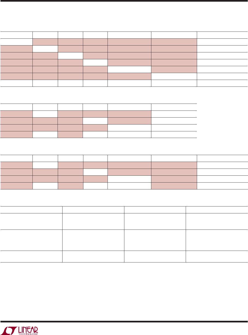
The LTC4066/LTC4066-1 reduce battery charge current
such that the sum of the battery charge current and the
load current does not exceed the programmed input current
limit (one-fi fth of the programmed input current limit when
HPWR is low, see Figure 2). The battery charge current
goes to zero when load current exceeds the programmed
input current limit (one-fi fth of the limit when HPWR is
low). If the load current is greater than the current limit, the
output voltage will drop to just under the battery voltage
where the ideal diode circuit will take over and the excess
load current will be drawn from the battery.
Programming Current Limit
The formula for input current limit is:
I
R
V
V
R
CL
CLPROG
CLPROG
CLPROG
=
⎛
⎝
⎜
⎞
⎠
⎟
=
1000 1000
•
where V
CLPROG
is the CLPROG pin voltage and R
CLPROG
is
the total resistance from the CLPROG pin to ground.
For example, if typical 500mA current limit is required,
calculate:
R
V
mA
k
CLPROG
==
1
500
1000 2•
I
LOAD
(mA)
0
CURRENT (mA)
300
400
600
500
I
IN
400
4066 F02a
200
100
–100
0
100
200
300
600500
I
LOAD
I
BAT
CHARGING
I
BAT
(IDEAL DIODE)
I
LOAD
(mA)
0
CURRENT (mA)
60
80
120
100
I
IN
80
4066 F02a
40
20
–20
0
20
40
60
120100
I
LOAD
I
BAT
CHARGING
I
BAT
(IDEAL DIODE)
I
LOAD
(mA)
0
CURRENT (mA)
300
400
600
500
I
IN
400
4055 F02c
200
100
–100
0
100
200
300
600500
I
LOAD
I
BAT
CHARGING
I
BAT
(IDEAL DIODE)
I
BAT
= I
CHG
I
BAT
= I
CL
– I
OUT
(2a) High Power Mode/Full Charge
R
PROG
= 100k and R
CLPROG
= 2k
(2b) Low Power Mode/Full Charge
R
PROG
= 100k and R
CLPROG
= 2k
(2c) High Power Mode with
I
CL
= 500mA and I
CHG
= 250mA
R
PROG
= 200k and R
CLPROG
= 2k
Figure 2. Input and Battery Currents as a Function of Load Current