PROGRAMMABLE FANOUT BUFFER 22 REVISION D 07/13/15
5P1103 DATASHEET
Table 22 Nominal Voltage Divider Values vs Driver VDD
shows resistor values that ensure the maximum drive level for
the CLKIN port is not exceeded for all combinations of 5%
tolerance on the driver VDD, the Vddo_0 and 5% resistor
tolerances. The values of the resistors can be adjusted to
reduce the loading for slower and weaker LVCMOS driver by
increasing the impedance of the R1-R2 divider. To assist this
assessment, the total load on the driver is included in the
table.
Table 22:Nominal Voltage Divider Values vs Driver VDD
HCSL Differential Clock Input Interface
CLKIN/CLKINB will accept DC coupled HCSL signals.
CLKIN, CLKINB Input Driven by an HCSL Driver
3.3V Differential LVPECL Clock Input Interface
The logic levels of 3.3V LVPECL and LVDS can exceed VIH
max for the CLKIN/B pins. Therefore the LVPECL levels must
be AC coupled to the differential input and the DC bias
restored with external voltage dividers. A single table of bias
resistor values is provided below for both for 3.3V LVPECL
and LVDS. Vbias can be VDDD, V
DDOX
or any other available
voltage at the receiver that is most conveniently accessible in
layout.
CLKIN, CLKINB Input Driven by a 3.3V LVPECL Driver
LVCMOS Driver VDD Ro+Rs R1 R2 Vrx (peak) Ro+Rs+R1+R2
3.3 50.0 130 75 0.97 255
2.5 50.0 100 100 1.00 250
1.8 50.0 62 130 0.97 242
Zo=50ohm
Zo=50ohm
CLKIN
CLKINB
Receiver
Q
nQ
+3.3V LVPECL
Driver
Zo=50ohm
Zo=50ohm
Receiver
R9 R10
50ohm
50ohm
Vbias
Rpu1 Rpu2
CLKIN
CLKINB
RTT
50ohm
C5
0.01µF
C6
0.01µF
R15
4.7kohm
R13
4.7kohm
REVISION D 07/13/15 23 PROGRAMMABLE FANOUT BUFFER
5P1103 DATASHEET
CLKIN, CLKINB Input Driven by an LVDS Driver
Table 23:Bias Resistors for 3.3V LVPECL and LVDS Drive to CLKIN/B
2.5V Differential LVPECL Clock Input Interface
The maximum DC 2.5V LVPECL voltage meets the VIH max
CLKIN requirement. Therefore 2.5V LVPECL can be
connected directly to the CLKIN terminals without AC coupling
CLKIN, CLKINB Input Driven by a 2.5V LVPECL Driver
LVDS Driver
Zo=50ohm
Zo=50ohm
Receiver
Rterm
100ohm
Vbias
Rpu1 Rpu2
CLKIN
CLKINB
C1
0.1µF
C2
0.1µF
R1
4.7kohm
R2
4.7kohm
Vbias
(V)
Rpu1/2
(kohm)
CLKIN/B Bias Voltage
(V)
3.3 22 0.58
2.5 15 0.60
1.8 10 0.58
+2.5V LVPECL
Driver
Zo=50ohm
Zo=50ohm
R1 R2
50ohm
50ohm
RTT
18ohm
Receiver
CLKIN
CLKINB
PROGRAMMABLE FANOUT BUFFER 24 REVISION D 07/13/15
5P1103 DATASHEET
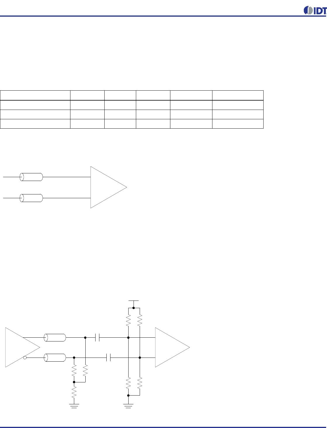
LVDS Driver Termination
For a general LVDS interface, the recommended value for the
termination impedance (Z
T
) is between 90. and 132. The
actual value should be selected to match the differential
impedance (Zo) of your transmission line. A typical
point-to-point LVDS design uses a 100
parallel resistor at the
receiver and a 100
. differential transmission-line
environment. In order to avoid any transmission-line reflection
issues, the components should be surface mounted and must
be placed as close to the receiver as possible. The standard
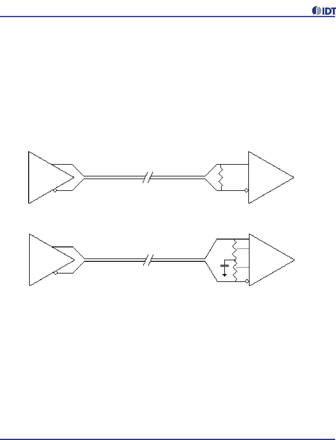
termination schematic as shown in figure
Standard
Termination
or the termination of figure Optional Termination
can be used, which uses a center tap capacitance to help filter
common mode noise. The capacitor value should be
approximately 50pF. In addition, since these outputs are LVDS
compatible, the input receiver's amplitude and common-mode
input range should be verified for compatibility with the IDT
LVDS output. If using a non-standard termination, it is
recommended to contact IDT and confirm that the termination
will function as intended. For example, the LVDS outputs
cannot be AC coupled by placing capacitors between the
LVDS outputs and the 100 ohm shunt load. If AC coupling is
required, the coupling caps must be placed between the 100
ohm shunt termination and the receiver. In this manner the
termination of the LVDS output remains DC coupled
LVDS
Driver
LVDS
Driver
LVDS
Receiver
LVDS
Receiver
Z
T
C
Z
O
Z
T
Z
O
Z
T
Z
T
2
Z
T
2
Standard Termination
Optional Termination

5P1103A000NLGI

Mfr. #:
Manufacturer:
IDT
Description:
Clock Buffer 2 to 4 Output OTP 1.8 to 3.3V Prog Out
Lifecycle:
New from this manufacturer.
Delivery:
DHL FedEx Ups TNT EMS
Payment:
T/T Paypal Visa MoneyGram Western Union

Products related to this Datasheet