©2013 Silicon Storage Technology, Inc. DS-20005014B 11/2013
16
16 Mbit Multi-Purpose Flash Plus
SST39WF1601 / SST39WF1602
Data Sheet
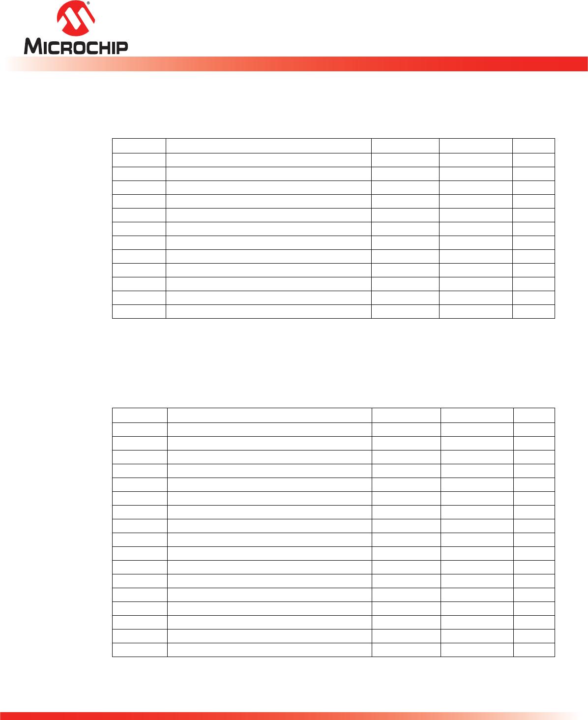
Table 12: DC Operating Characteristics V
DD
= 1.65-1.95V
1
Symbol Parameter
Limits
Test ConditionsMin Max Units
I
DD
Power Supply Current Address input=V
ILT
/V
IHT,
at f=5 MHz,
V
DD
=V
DD
Max
Read 10 mA CE#=V
IL
, OE#=WE#=V
IH
, all I/Os
open
Program and Erase 25 mA CE#=WE#=V
IL
, OE#=V
IH
I
SB
Standby V
DD
Current
2
40 µA CE#=V
IHC
,V
DD
=V
DD
Max
I
ALP
Auto Low Power 40 µA CE#=V
ILC
,V
DD
=V
DD
Max
All inputs=V
SS
or V
DD,
WE#=V
IHC
I
LI
Input Leakage Current 1 µA V
IN
=GND to V
DD
,V
DD
=V
DD
Max
I
LIW
Input Leakage Current
on WP# pin and RST#
10 µA WP#=GND to V
DD
or RST#=GND to
V
DD
I
LO
Output Leakage Current 1 µA V
OUT
=GND to V
DD
,V
DD
=V
DD
Max
V
IL
Input Low Voltage 0.2V
DD
VV
DD
=V
DD
Min
V
IH
Input High Voltage 0.8V
DD
VV
DD
=V
DD
Max
V
OL
Output Low Voltage 0.1 V I
OL
=100 µA, V
DD
=V
DD
Min
V
OH
Output High Voltage V
DD
-0.1 V I
OH
=-100 µA, V
DD
=V
DD
Min
T12.0 20005014
1. Typical conditions for the Active Current shown on the front page of the data sheet are average values at 25°C
(room temperature), and V
DD
= 1.8V. Not 100% tested.
2. For all SST39WF160x commercial and industrial devices, I
SB
typical is under 5 µA.
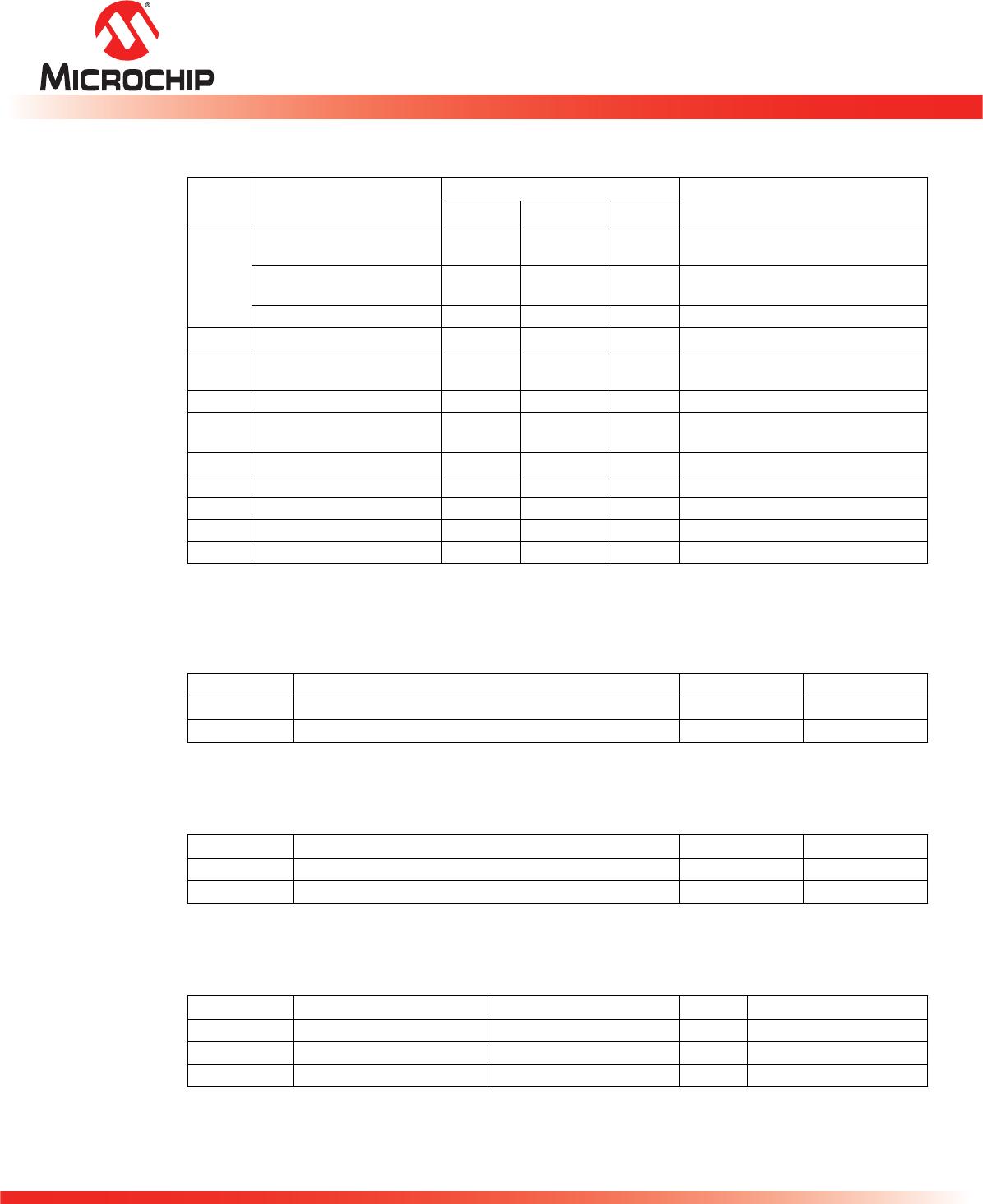
Table 13: Recommended System Power-up Timings
Symbol Parameter Minimum Units
T
PU-READ
1
1. This parameter is measured only for initial qualification and after a design or process change that could affect this
parameter.
Power-up to Read Operation 100 µs
T
PU-WRITE
1
Power-up to Program/Erase Operation 100 µs
T13.0 20005014
Table 14: Capacitance (T
A
= 25°C, f=1 Mhz, other pins open)
Parameter Description Test Condition Maximum
C
I/O
1
1. This parameter is measured only for initial qualification and after a design or process change that could affect this
parameter.
I/O Pin Capacitance V
I/O
=0V 12pF
C
IN
1
Input Capacitance V
IN
=0V 6pF
T14.0 20005014
Table 15: Reliability Characteristics
Symbol Parameter Minimum Specification Units Test Method
N
END
1,2
1. This parameter is measured only for initial qualification and after a design or process change that could affect this
parameter.
2. N
END
endurance rating is qualified as a 10,000 cycle minimum for the whole device. A sector- or block-level rating would
result in a higher minimum specification.
Endurance 10,000 Cycles JEDEC Standard A117
T
DR
1
Data Retention 100 Years JEDEC Standard A103
I
LTH
1
Latch Up 100 + I
DD
mA JEDEC Standard 78
T15.0 20005014
©2013 Silicon Storage Technology, Inc. DS-20005014B 11/2013
17
16 Mbit Multi-Purpose Flash Plus
SST39WF1601 / SST39WF1602
Data Sheet
AC Characteristics
Table 16: Read Cycle Timing Parameters V
DD
= 1.65-1.95V
Symbol Parameter Min Max Units
T
RC
Read Cycle Time 70 ns
T
CE
Chip Enable Access Time 70 ns
T
AA
Address Access Time 70 ns
T
OE
Output Enable Access Time 35 ns
T
CLZ
1
1. This parameter is measured only for initial qualification and after a design or process change that could affect this
parameter.
CE# Low to Active Output 0 ns
T
OLZ
1
OE# Low to Active Output 0 ns
T
CHZ
1
CE# High to High-Z Output 40 ns
T
OHZ
1
OE# High to High-Z Output 40 ns
T
OH
1
Output Hold from Address Change 0 ns
T
RP
1
RST# Pulse Width 500 ns
T
RHR
1
RST# High before Read 50 ns
T
RY
1,2
2. This parameter applies to Sector-Erase, Block-Erase and Program operations.
This parameter does not apply to Chip-Erase operations.
RST# Pin Low to Read Mode 20
3
3. This parameter is 100 µs if reset after an Erase operation.
µs
T16.0 20005014
Table 17: Program/Erase Cycle Timing Parameters
Symbol Parameter Min Max Units
T
BP
Word-Program Time 40 µs
T
AS
Address Setup Time 0 ns
T
AH
Address Hold Time 50 ns
T
CS
WE# and CE# Setup Time 0 ns
T
CH
WE# and CE# Hold Time 0 ns
T
OES
OE# High Setup Time 0 ns
T
OEH
OE# High Hold Time 10 ns
T
CP
CE# Pulse Width 50 ns
T
WP
WE# Pulse Width 50 ns
T
WPH
1
1. This parameter is measured only for initial qualification and after a design or process change that could affect this
parameter.
WE# Pulse Width High 30 ns
T
CPH
1
CE# Pulse Width High 30 ns
T
DS
Data Setup Time 50 ns
T
DH
1
Data Hold Time 0 ns
T
IDA
1
Software ID Access and Exit Time 150 ns
T
SE
Sector-Erase 50 ms
T
BE
Block-Erase 50 ms
T
SCE
Chip-Erase 200 ms
T17.0 20005014
©2013 Silicon Storage Technology, Inc. DS-20005014B 11/2013
18
16 Mbit Multi-Purpose Flash Plus
SST39WF1601 / SST39WF1602
Data Sheet
Figure 4: Read Cycle Timing Diagram
Figure 5: WE# Controlled Program Cycle Timing Diagram
1297 F03.1
ADDRESS A
19-0
DQ
15-0
WE#
OE#
CE#
T
CE
T
RC
T
AA
T
OE
T
OLZ
V
IH
HIGH-Z
T
CLZ
T
OH
T
CHZ
HIGH-Z
DATA VALIDDATA VALID
T
OHZ
1297 F04.1
ADDRESS A
19-0
DQ
15-0
T
DH
T
WPH
T
DS
T
WP
T
AH
T
AS
T
CH
T
CS
CE#
SW0 SW1 SW2
5555 2AAA 5555 ADDR
XXAA XX55 XXA0 DATA
INTERNAL PROGRAM OPERATION STARTS
WORD
(ADDR/DATA)
OE#
WE#
T
BP
Note: WP# must be held in proper logic state (V
IL
or
V
IH
) 1 µs prior to and 1µs after the command sequence.
X can be V
IL
or V
IH,
but no other value.

SST39WF1601-70-4I-MAQE-T

Mfr. #:
Manufacturer:
Microchip Technology
Description:
NOR Flash 1.65V to 1.95V 16Mbit Multi-Prps Fl
Lifecycle:
New from this manufacturer.
Delivery:
DHL FedEx Ups TNT EMS
Payment:
T/T Paypal Visa MoneyGram Western Union