AD1953
–15–
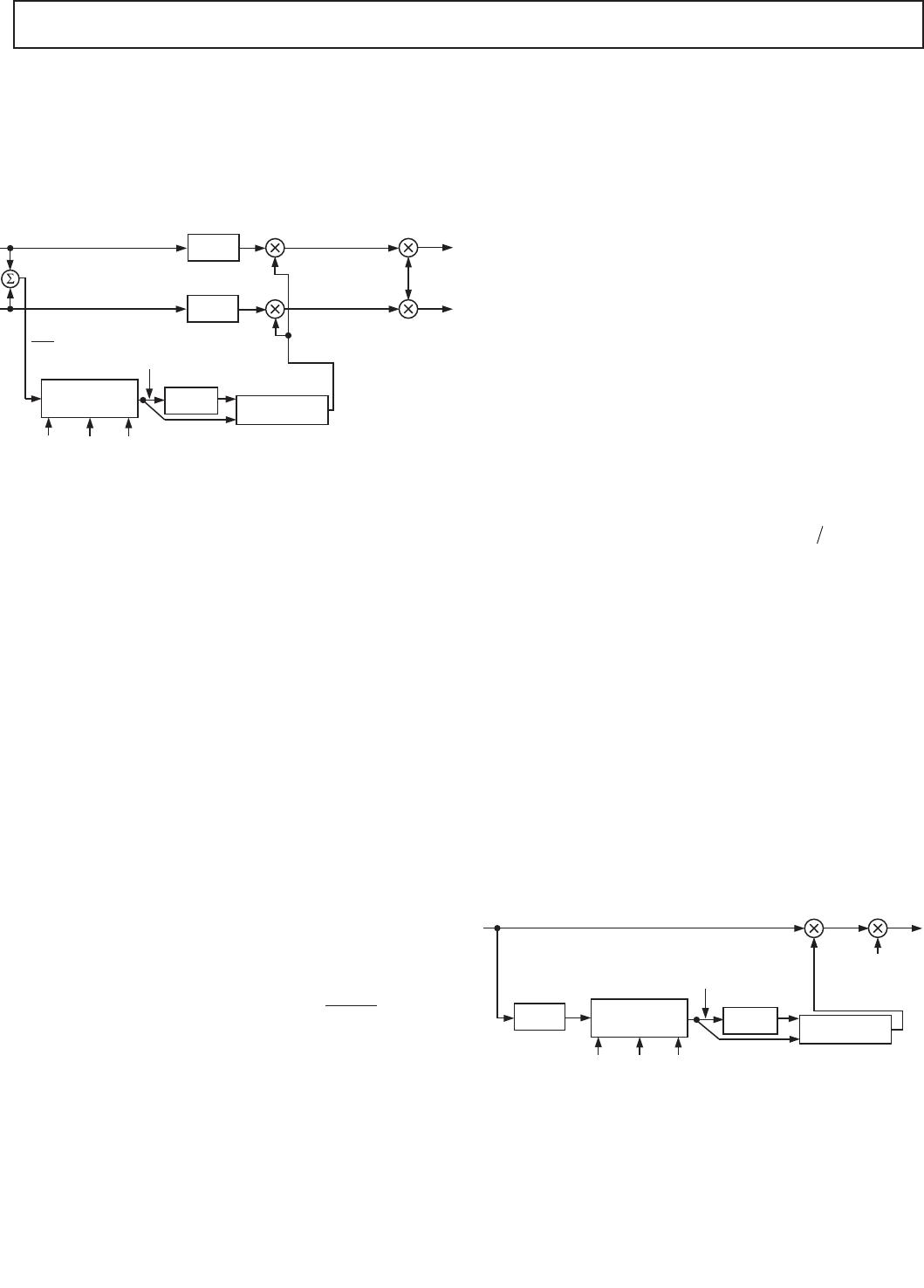
The spread_level is a linear number in 2.20 format that multiplies
the processed left-right signal before it is added to or subtracted
from the main channels. The parameter alpha_spread is related to
the cutoff frequency of the first-order low-pass filter by the equation
Alpha spread EXP
spread freq
f
S
_.
–. _
=
××
10
20 π
where EXP is the exponential operator, spread_freq is the low-pass
cutoff in Hz, and f
S
is the audio sampling rate.
Note that the stereo spreading algorithm assumes that frequencies
below 1 kHz are present in the main satellite speakers. In some
systems, the crossover frequency between the satellite and
subwoofer speakers is quite high (> 500 Hz). In this case, the
stereo spreading algorithm will not be effective, as the frequencies
that contribute to the spreading effect will be coming mostly from
the subwoofer, which is a mono source.
Delay
Each of the three DAC channels has a delay block that allows
the user to introduce a delay of up to 165 audio samples. The
delay values are programmed by entering the delay (in samples)
into the appropriate location of the parameter RAM. With a
44.1 kHz sample rate, a delay of 165 samples corresponds to a
time delay of 3.74 ms. Since sound travels at approximately
1 foot/ms, this can be used to compensate for speaker place-
ments that are off by as much as 3.74 feet.
An additional 100 samples of delay are used in the look-ahead
portion of the compressor/limiter, but only for the main two
channels. This can be used to increase the total delay for the left
and right channels to 265 samples, or 6 ms at 44.1 kHz.
Main Compressor/Limiter
The compressor used in the AD1953 is quite sophisticated and
is comparable in many ways to professional compressor/limiters
used in the professional audio and broadcast fields. It uses rms/
peak detection with adjustable attack/hold/release, look-ahead
compression, and table-based entry of the input/output curve for
complete flexibility.
The AD1953 uses two compressor/limiters, one in the subwoofer
DAC and one in the main left/right DAC. It is well known that
having independent compressors operating over different frequency
ranges results in a superior perceived sound. With a single-band
compressor, loud bass information will modulate the gain of the
entire audio signal, resulting in suboptimal maximum perceived
loudness as well as gain pumping or modulation effects. With
independent compressors operating separately on the low and
high frequencies, this problem is dramatically reduced. If the
AD1953 is being operated in 2-channel mode, an extra path is
added so that the subwoofer channel can be added back into the
main channel. This maintains the advantage of using a 2-band
compressor, even in a 2.0 system configuration.
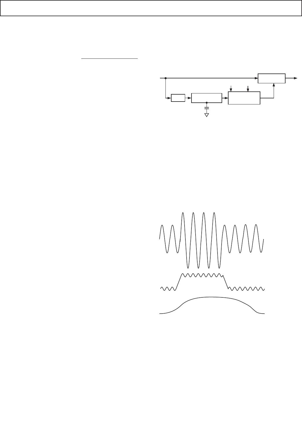
Figure 7 shows the traditional basic analog compressor/limiter.
It uses a voltage controlled amplifier to adjust gain and a feed-
forward detector path using an rms detector with adjustable
time constants, followed by a nonlinear circuit to implement the
desired input/output relationship. A simple compressor will have
a single threshold above which the gain is reduced. The amount
of compression above the threshold is called the compression
ratio and is defined as dB change in input/dB change in output.
For example, if the input to a 2:1 compressor is increased by
2 dB, the output will rise by 1 dB for signals above the threshold.
A single “hard” threshold results in more audible behavior than
a so-called “soft-knee” compressor, where the compression is
introduced more gradually. In an analog compressor, the soft-knee
characteristic is usually made by using diodes in their exponential
turn-on region.
FILTER
RMS DETECTOR
WITH dB OUT
COMPRESSION
CURVE NON-
LINEAR CIRCUITS
THRESHOLD
SLOPE
VCA WITH EXP
CONTROL
OUT
Figure 7. Analog Compressor
The best analog compressors use rms detection as the signal
amplitude detector. RMS detectors are the only class of detec-
tors that are not sensitive to the phase of the harmonics in a
complex signal. The ear also bases its loudness judgment on the
overall signal power. Using an rms detector therefore results in
the best audible performance. Compressors that are based on
peak detection, while good for preventing clipping, are generally
quite poor when it comes to audible performance.
RMS detectors have a certain time constant that determines
how rapidly they can respond to transient signals. There is always
a trade-off between speed of response and distortion. Figure 8
shows this trade-off.
INPUT WAVEFORM
COMPRESSOR ENVELOPE –
FAST TIME CONSTANT
COMPRESSOR ENVELOPE –
SLOW TIME CONSTANT
Figure 8. Effect of RMS Time Constant on Distortion
In the case of a fast-responding rms detector, the detector enve-
lope will have a signal component in addition to the desired dc
component. This signal component (which, for an rms detector,
is at twice the input frequency) will result in harmonic distortion
when multiplied by this detector signal.
The AD1953 uses a modified rms algorithm to improve the
relationship between acquisition time and distortion. It uses a
peak-riding circuit together with a hold circuit to modify the rms
signal, as shown in Figure 9. Figure 8 shows two envelopes—one
with the harmonic distortion and another, flatter envelope,
which is produced by the AD1953.
REV. A
AD1953
–16–
INPUT WAVEFORM
HOLD TIME, SPI-
PROGRAMMABLE
RELEASE TIME, SPI-
PROGRAMMABLE
Figure 9. Using the Hold and Release Time Feature
Using this idea of a modified rms algorithm, the true rms value
is still obtained for all but the lowest frequency signals, while the
distortion due to rms ripple is reduced. It also allows the user to
set the hold and release times of the compressor independently.
The detector path of the AD1953 is shown in Figure 10. The rms
detector is controlled by three parameters stored in parameter
RAM: the rms time constant, the hold time, and the release rate.
The log output of the rms detector is applied to a look-up table
with interpolation. The higher bits of the rms output form an
offset into this table, and the lower bits are used to interpolate
between the table entries to form a high precision gain word.
The look-up table resides in the parameter RAM and is loaded
by the user to give the desired curve. The look-up table contains
33 data locations, and the LSB of the address into the look-up
table corresponds to a 3 dB change in the amplitude of the detec-
tor signal. This gives the user the ability to program an input/
output curve over a 99 dB range. For the main compressor, the
table resides in locations 110 to 142 in the SPI parameter RAM.
LOOK-UP TABLE
LINEAR
INTERPOLATION
MODIFIED RMS
DETECTOR WITH
LOG OUTPUT
OUTPUT TO
GAIN STAGE
HIGH BITS (1LSB = 3dB)
LOW BITS
TIME
CONSTANT
HOLD
RELEASE
Figure 10. Gain Derived from Interpolated Look-Up Table
One subtlety of the table look-up involves the difference between
the rms value of a sine wave and that of a square wave. If a
full-scale square wave is applied to the AD1953, the rms value of
this signal will be 3 dB higher than the rms value of a 0 dBFS sine
wave. Therefore, the table will range from +9 dB (location 142)
to –87 dB (location 110).
The entries in the table are linear gain words in 2.20 format.
Figure 11 shows an example of the table entries for a simple
above-threshold compressor.
INPUT LEVEL – 3dB/TABLE ENTRY
OUTPUT LEVEL – dB
INPUT LEVEL – 3dB/TABLE ENTRY
LINEAR GAIN
1.0
DESIRED
COMPRESSION
CURVE
Figure 11. Example of Table Entry for a Given
Compression Curve
Note that the maximum gain that can be entered in the table is 2.0
(minus 1 LSB). If more gain is required, the entire compression
curve may be shifted upward by using the post-compression gain
block following the compressor/limiter.
The AD1953 compressor/limiter also includes a look-ahead
compression feature. The idea behind look-ahead compression
is to prevent compressor overshoots by applying some digital
delay to the signal before the gain-control multiplier, but not to
the detector path. In this way, the detector can acquire the new
amplitude of the input signal before the signal actually reaches
the multiplier. A comparison of a tone burst fed to a conventional
compressor versus a look-ahead compressor is shown in Figure 12.
CONVENTIONAL COMPRESSOR GAIN
LOOK-AHEAD COMPRESSOR GAIN
HOLD TIME
Figure 12. Conventional Compression vs. Look-Ahead
Compression
REV. A
AD1953
–17–
In the look-ahead compressor, the gain has already been reduced
by the time the tone-burst signal arrives at the multiplier input.
Note that when using a look-ahead compressor, it is impor-
tant to set the detector hold time to a value that is at least the
same as the look-ahead delay time, or else the compressor
release will start too soon, resulting in an expanded “tail” of a
tone burst signal. The complete flow of the left/right dynamics
processor is shown in Figure 13.
LOOK-UP
TABLE
LINEAR
INTERPOLATION
MODIFIED RMS
DETECTOR WITH
LOG OUTPUT
HIGH BITS (1LSB = 3dB)
LOW BITS
TIME
CONSTANT
HOLD
RELEASE
DELAY
DELAY
SPI-PROGRAMMABLE
LOOK-AHEAD DELAY
POST-COMPRESSION
GAIN, SPI-
PROGRAMMABLE
UP TO 30dB
2
(L+R)
Figure 13. Complete Dynamics Flow, Main Channels
The detector path works from a sum of left and right channels
((L+R)/2). This is the normal way that compressors are built,
and it counts on the fact that the main instruments in any stereo
mix are seldom recorded deliberately out of phase, especially in
the lower frequencies, which tend to dominate the energy spectrum
of real music.
The compressor is followed by a block known as post-compression
gain. Most compressors are used to reduce the dynamic range of
music by lowering the gain during loud signal passages. This
results in an overall loss of volume. This loss can be made up by
introducing gain after the compressor. In the AD1953, the
coefficient format used is 2.20, which has a maximum floating-
point representation of slightly less than 2.0. This means the
maximum gain that can be achieved in a single instruction is 6 dB.
To get more gain, the program in the AD1953 uses a cascade
of five multipliers to achieve up to 30 dB of post-compression gain.
To program the compressor/limiter, the following formulas may
be used to determine the 22-bit numbers (in 2.20 format) to be
entered into the parameter RAM.
RMS Time Constant
This can be best expressed by entering the time constant in
terms of dB/sec “raw” release rate (without the peak-riding circuit).
The attack rate is a rather complicated formula that depends on
the change in amplitude of the input sine wave.
rms tconst parameter
release rate
f
S
__ .
.
=
×
10 10
10 0
where
rms_tconst_parameter = fractional number to enter into
the
SPI RAM (after converting to 22-bit 2.20 format)
release_rate = release rate of the raw rms detector in dB/sec. This
must be negative. f
S
= audio sampling rate.
RMS Hold Time
rms holdtime parameter f hold time
S
_ _ int _
()
where
rms_holdtime_parameter = integer number to enter into the SPI RAM
f
S
= audio sample rate
Hold_time = absolute time to wait before starting the release
ramp-down of the detector output
int() = integer part of expression
RMS Release Rate
rms decay parameter rms decay_ _ int _ / .=
()
1 096
Where rms_decay_parameter = decimal integer number to enter
into the SPI RAM
rms_decay = decay rate in dB/sec
int() = integer part of expression
Look-Ahead Delay
Lookahead delay parameter Lookahead delay f
S
__ _
Where Lookahead_delay = predictive compressor delay in abso-
lute time
f
S
= audio sample rate
The maximum Lookahead_delay_parameter value is 100.
Post-Compression Gain
Post compression gain parameter
Post compression gain linear
___
___
=
()
15
Where Post_compression gain_linear is the linear post-compression
gain
^ = raise to the power
Subwoofer Compressor/Limiter
The subwoofer compressor/limiter differs from the left/right
compressor in the following ways:
1. The subwoofer compressor operates on a weighted sum of left
and right inputs (aa × Left + bb × Right), where aa and bb are
both programmable.
2. The detector input has a biquad filter in series with the input
in order to implement frequency-dependent compression
thresholds.
3. There is no predictive compression, as presumably the input
signals are filtered to pass only low frequencies, and therefore
transient overshoots are not a problem.
The subwoofer compressor signal flow is shown in Figure 14.
LOOK-UP
TABLE
LINEAR
INTERPOLATION
MODIFIED RMS
DETECTOR WITH
LOG OUTPUT
HIGH BITS (1LSB = 3dB)
LOW BITS
TIME
CONSTANT
HOLD
RELEASE
V
IN
_SUB = K1 LEFT_IN + K2 RIGHT_IN
POST-COMPRESSION
GAIN, SPI-
PROGRAMMABLE
UP TO 30dB
BIQUAD
FILTER
Figure 14. Signal Flow for Subwoofer Compressor
The biquad filter before the detector can be used to implement
a frequency-dependent compression threshold. For example,
assume that the overload point of the woofer is strongly fre-
quency-dependent. In this case, one would have to set the
compressor threshold to a value that corresponded to the most
sensitive overload frequency of the woofer. If the input signal
happened to be mostly in a frequency range where the woofer
REV. A

AD1953YSTZRL

Mfr. #:
Manufacturer:
Analog Devices Inc.
Description:
Audio DSPs IC Digital Audio Processor
Lifecycle:
New from this manufacturer.
Delivery:
DHL FedEx Ups TNT EMS
Payment:
T/T Paypal Visa MoneyGram Western Union

Products related to this Datasheet