XRD98L23
28
Rev. 1.00
Serial Load Control Registers
The serial load registers are controlled by a three wire
serial interface through the bi-directional parallel port to
reduce the pin count of this device. When SYNCH is set
to high, the output bus is tri-stated and the serial
interface is activated. DB7/LD, DB5/SCLK and DB6/
SDATA are the three input signals that control this
process. The DB7/LD signal is set low to initiate the
loading of the internal registers.
There are internal registers that are accessed via an 11-
bit data string. Data is shifted in on the rising edge of
SCLK and loaded to the registers on the rising edge of
LD. The data on pin DB6/SDATA is latched automati-
cally after eleven DB5/SCLKs have been counted. If
eleven clocks are not present on DB5/SCLK before the
DB7/LD signal returns high, no data will be loaded into
the internal registers. If more than 11 clocks are
present on DB5/SCLK, the additional clocks will be
ignored. The data corresponding to the first eleven
DB5/SCLKs will be loaded only.
The first three MSBs choose which internal register will
be selected. The remaining 8 LSBs contain the data
needed for programming the internal register for a
particular configuration.
Power-Up State of the Internal Registers
The control register settings upon initial power-up are
for CIS, DC Coupled configuration (V
RT
is set to internal,
Input DC Reference=AGND and the input to the ADC is
selected through the RED channel). Gain is unity and
Offset is set to zero. The test modes are disabled in the
power-up state.
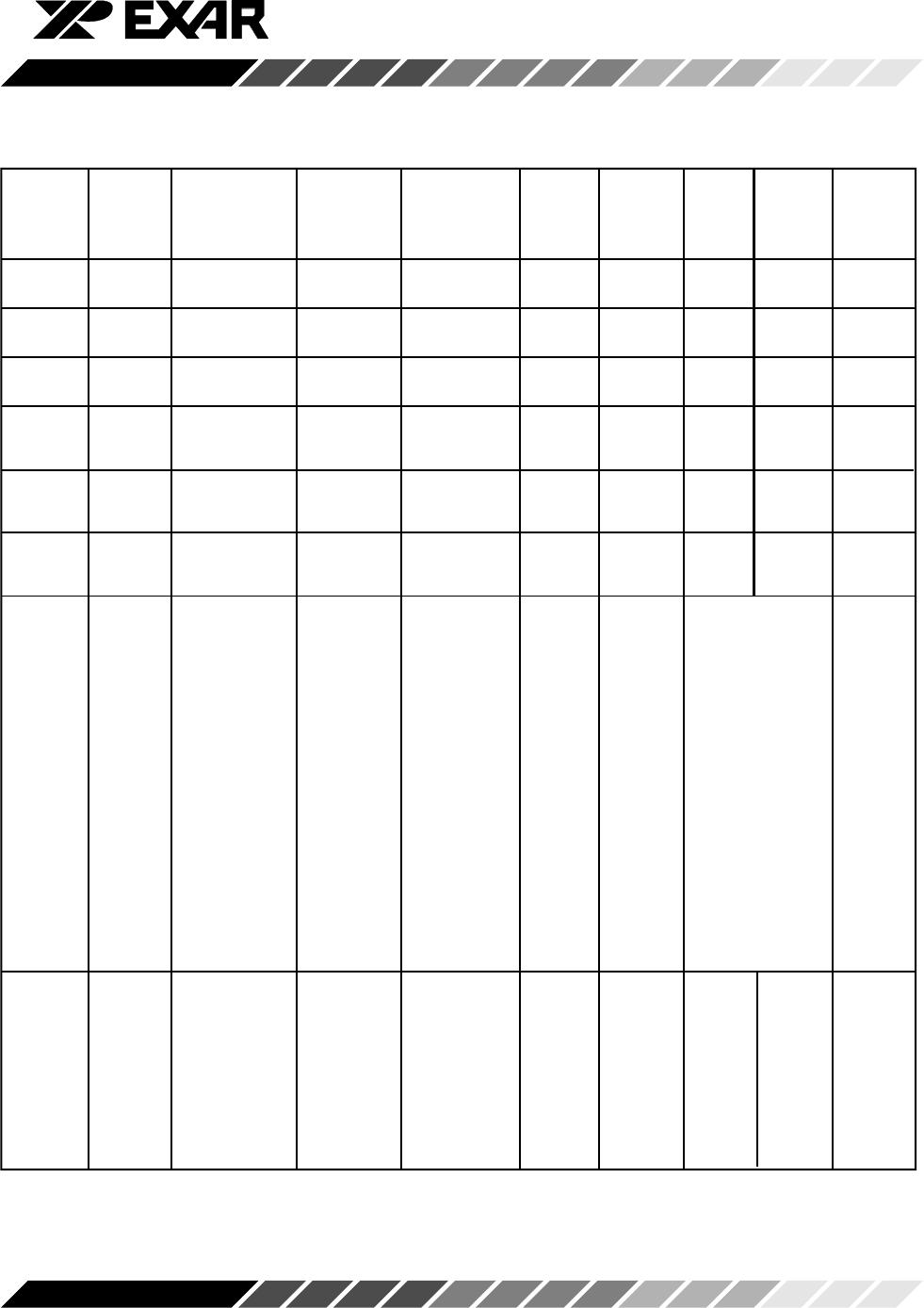
DB6/SDATA
DB5/SCLK
SYNCH
S2 S1 S0 D7 D2 D1 D0
DB7/LD
tdl
tdz
tsclkw
tds tdh
Figure 22. Write Timing