XRD98L23
6
Rev. 1.00
ELECTRICAL CHARACTERISTICS (CONT'D)
Test Conditions: AV
DD
=DV
DD
=3.3V, ADCCLK=10MHz, 50% Duty Cycle, T
A
=25°C unless otherwise specified.
Symbol Parameter Min. Typ. Max. Unit Conditions
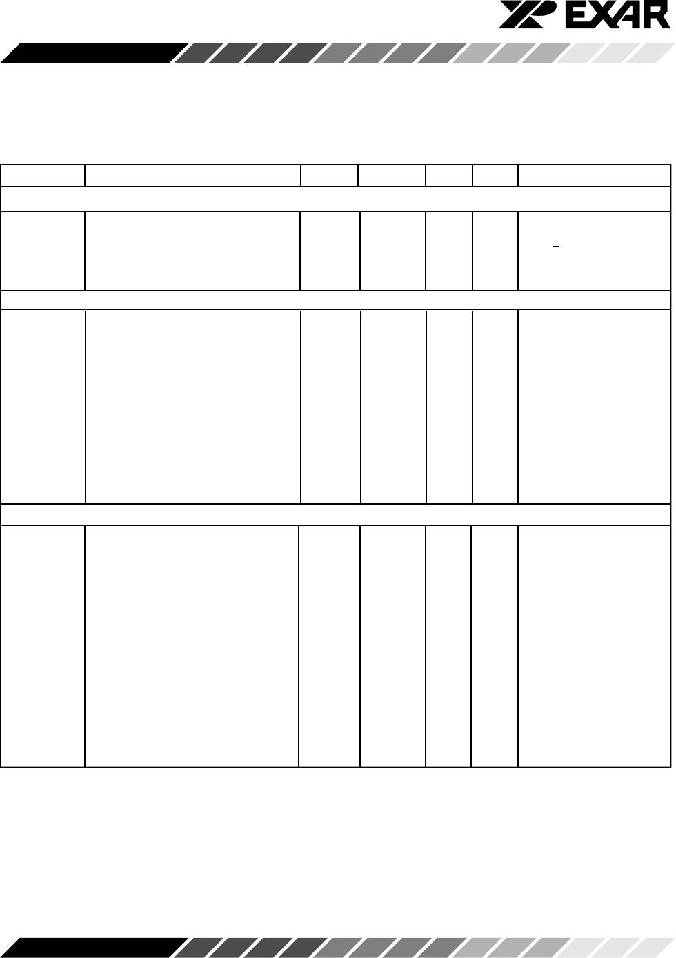
System Specifications (MUX + Buffer + PGA + ADC) Note 1
SYS
DNL
System DNL -1.0 ±0.5 +2.0 LSB No missing codes
SYS
LIN
System Linearity ±6.0 LSB
SYS
GE
System Gain Error -5.0 +5.0 %
IRN Input Referred Noise 1.5 mV
rms
Gain=1
Input Referred Noise 0.5 mV
rms
Gain=10
System Timing Specifications
tcklw ADCCLK Low Pulse Width 50 ns
tckhw ADCCLK High Pulse Width 50 ns
tckpd ADCCLK Period 100 ns
tsypw SYNCH Pulse Width 30 ns
trars Rising ADCCLK to rising 0 SYNCH must rise equal to
SYNCH or after ADCCLK, See Figure 18
tclpw CLAMP Pulse Width 30 ns Note 2
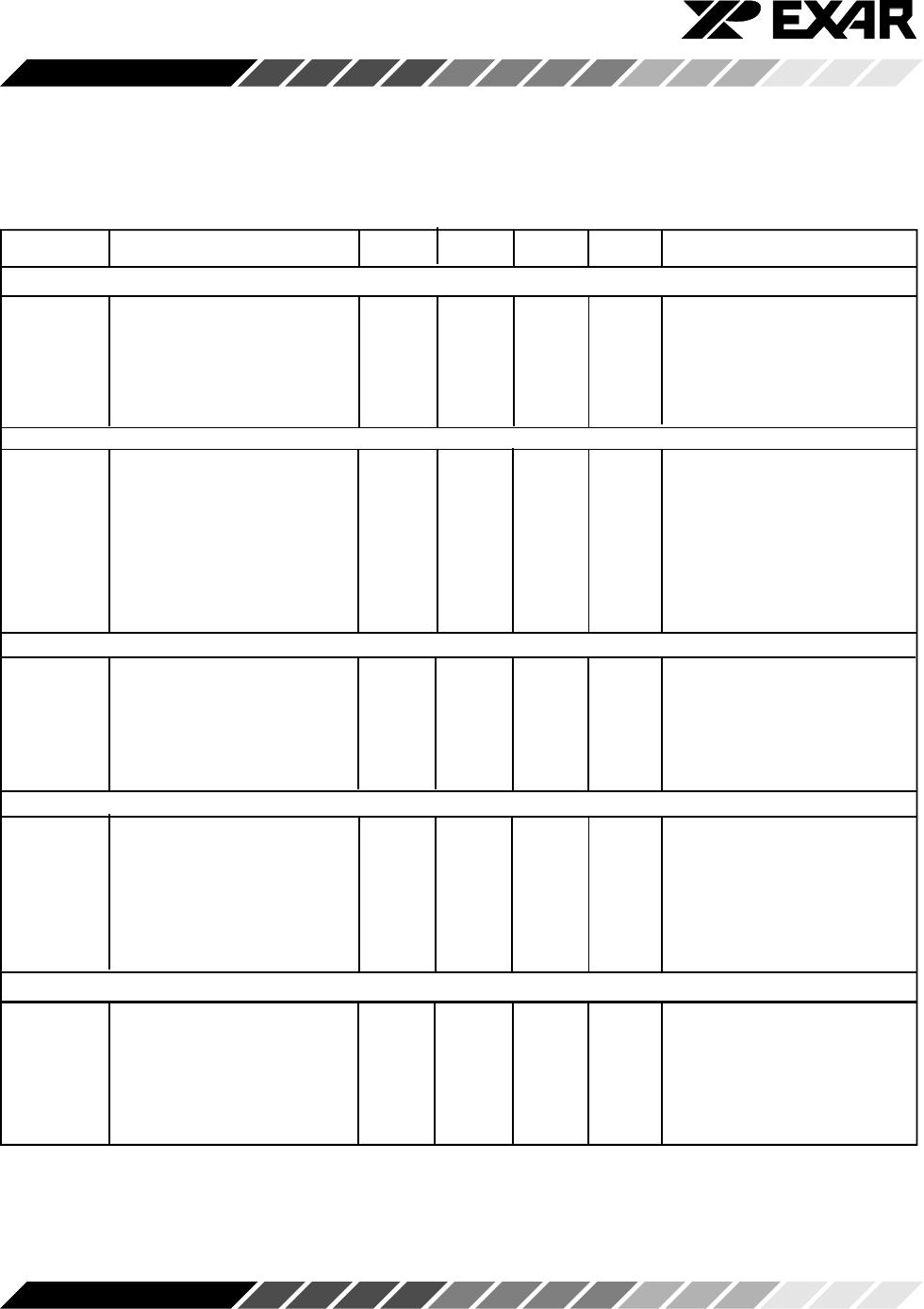
Write Timing Specifications
tsclkw SCLK Pulse Width 40 ns
tdz LD Low to SCLK High 20 ns
tds Input Data Set-up Time 20 ns
tdh Input Data Hold Time 0 ns
tdl SCLK High to LD High 50 ns
ADC Digital Output Specifications
tap Aperture Delay ns
tdv Output Data Valid 30 50 ns
tsa SYNCH to ADCCLK (3ch) 20 ns 3ch Pixel Md
tsa2 SYNCH to ADCCLK (2ch) 20 80 ns 2ch Pixel Md
tlat Latency 8 cycles Config 00, 11
tlat Latency 6 pixels Config 01, 10
Digital Input Specifications
V
IH
Input High Voltage AV
DD
-1.5 V
V
IL
Input Low Voltage 0.6 V
I
IH
High Voltage Input Current 5 µA
I
IL
Low Voltage Input Current 5 µA
C
IN
Input Capacitance 10 pF
Note 1: System performance is specified for typical digital system timing specifications.
Note 2: The actual minimum ‘tclpw’ is dependent on the external capacitor value, the CIS output impedance.
During ‘clamp’ operation, sufficient time needs to be allowed for the external capacitor to charge up to the
correct operating level. Refer to the description in Theory of Operation, CIS Config.