PCA85134 All information provided in this document is subject to legal disclaimers. © NXP Semiconductors N.V. 2014. All rights reserved.
Product data sheet Rev. 2 — 6 May 2014 38 of 53
NXP Semiconductors
PCA85134
Automotive 60 x 4 LCD segment driver for low multiplex rates
The SYNC line is provided to maintain the correct synchronization between all cascaded
PCA85134. Synchronization is guaranteed after a power-on reset. The only time that
SYNC
is likely to be needed is if synchronization is accidentally lost (for example, by noise
in adverse electrical environments or by defining a multiplex drive mode when PCA85134
with different SA0 levels are cascaded).
SYNC
is organized as an input/output pin. The output selection is realized as an
open-drain driver with an internal pull-up resistor. A PCA85134 asserts the SYNC
line at
the onset of its last active backplane signal and monitors the SYNC
line at all other times.
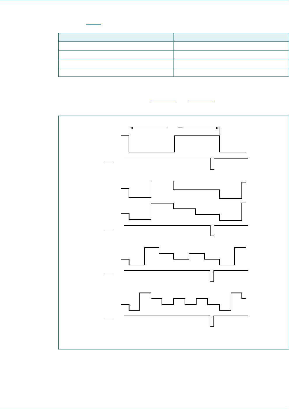
If synchronization in the cascade is lost, it is restored by the first PCA85134 to assert
SYNC
. The timing relationship between the backplane waveforms and the SYNC signal
for the various drive modes of the PCA85134 are shown in Figure 23
.
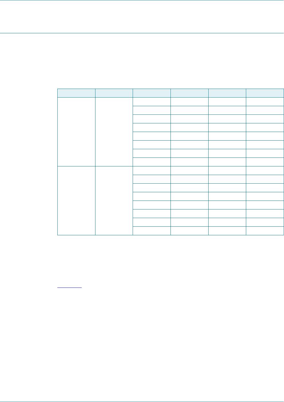
The contact resistance between the SYNC
on each cascaded device must be controlled.
If the resistance is too high, the device is not able to synchronize properly; this is
applicable to chip-on-glass applications. The maximum SYNC
contact resistance allowed
for the number of devices in cascade is given in Table 23
.
(1) Is master (OSC connected to V
SS
).
(2) Is slave (OSC connected to V
DD
).
Fig 22. Cascaded PCA85134 configuration
+267
0,&52
0,&52
6'$
6&/
&/.
26&
6<1&
VHJPHQWGULYHV
EDFNSODQHV
VHJPHQWGULYHV
3&$
$ $ $ 6$
6
9
66
9
66
9
''
'
9
/&'
/&'
9
''
9
/&'
6'$
6&/
6<1&
&/.
26&
%3WR%3
RSHQFLUFXLW
$ $ $ 6$
3&$
%3WR%3
5
W
U
&
E