PCA85134 All information provided in this document is subject to legal disclaimers. © NXP Semiconductors N.V. 2014. All rights reserved.
Product data sheet Rev. 2 — 6 May 2014 7 of 53
NXP Semiconductors
PCA85134
Automotive 60 x 4 LCD segment driver for low multiplex rates
The host microcontroller maintains the 2-line I
2
C-bus communication channel with the
PCA85134.
Biasing voltages for the multiplexed LCD waveforms are generated internally, removing
the need for an external bias generator. The internal oscillator is selected by connecting
pin OSC to V
SS
. The only other connections required to complete the system are the
power supplies (pins V
DD
, V
SS
, and V
LCD
) and the LCD panel selected for the application.
7.1 Power-On Reset (POR)
At power-on the PCA85134 resets to the following starting conditions:
All backplane and segment outputs are set to V
LCD
The selected drive mode is: 1:4 multiplex with
1
3
bias
Blinking is switched off
Input and output bank selectors are reset
The I
2
C-bus interface is initialized
The data pointer and the subaddress counter are cleared (set to logic 0)
The display is disabled (bit E = 0, see Table 12)
Remark: Do not transfer data on the I
2
C-bus for at least 1 ms after a power-on to allow
the reset action to complete.
7.2 LCD bias generator
Fractional LCD biasing voltages are obtained from an internal voltage divider consisting of
three impedances connected in series between V
LCD
and V
SS
. If the
1
2
bias voltage level
for the 1:2 multiplex drive mode configuration is selected, the center impedance is
bypassed by switch. The LCD voltage can be temperature compensated externally, using
the supply to pin V
LCD
.
Fig 4. Typical system configuration
+267
0,&52
&21752//(5
5

W
U
&
E
6'$
6&/
VHJPHQWGULYHV
EDFNSODQHV
/&'3
$1(/
XSWR
HOHPHQWV
3&$
9
'
'
9
6
6
9
66
DDD
9
/&'
9
/&'
9
''
$ $ 6$$
26&
PCA85134 All information provided in this document is subject to legal disclaimers. © NXP Semiconductors N.V. 2014. All rights reserved.
Product data sheet Rev. 2 — 6 May 2014 8 of 53
NXP Semiconductors
PCA85134
Automotive 60 x 4 LCD segment driver for low multiplex rates
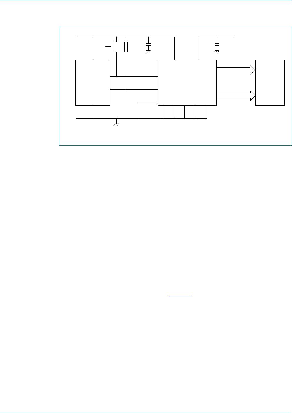
7.3 LCD voltage selector
The LCD voltage selector coordinates the multiplexing of the LCD in accordance with the
selected LCD drive configuration. The operation of the voltage selector is controlled by the
mode-set command from the command decoder. The biasing configurations that apply to
the preferred modes of operation, together with the biasing characteristics as functions of
V
LCD
and the resulting discrimination ratios (D) are given in Table 6.
Discrimination is a term which is defined as the ratio of the on and off RMS voltage across
a segment. It can be thought of as a measurement of contrast.
A practical value for V
LCD
is determined by equating V
off(RMS)
with a defined LCD
threshold voltage (V
th(off)
), typically when the LCD exhibits approximately 10 % contrast. In
the static drive mode, a suitable choice is V
LCD
>3V
th(off)
.
Multiplex drive modes of 1:3 and 1:4 with
1
2
bias are possible but the discrimination and
hence the contrast ratios are smaller.
Bias is calculated by , where the values for a are
a = 1 for
1
2
bias
a = 2 for
1
3
bias
The RMS on-state voltage (V
on(RMS)
) for the LCD is calculated with Equation 1:
(1)
where the values for n are
n = 1 for static drive mode
n = 2 for 1:2 multiplex drive mode
n = 3 for 1:3 multiplex drive mode
n = 4 for 1:4 multiplex drive mode
The RMS off-state voltage (V
off(RMS)
) for the LCD is calculated with Equation 2:
(2)
Discrimination is the ratio of V
on(RMS)
to V
off(RMS)
and is determined from Equation 3:
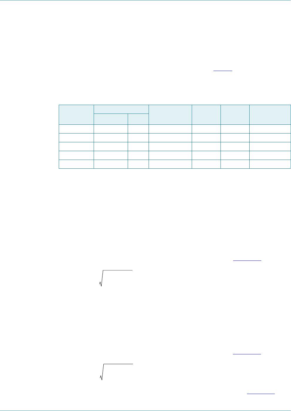
Table 6. Biasing characteristics
LCD drive
mode
Number of: LCD bias
configuration
Backplanes Levels
static 1 2 static 0 1
1:2 multiplex 2 3
1
2
0.354 0.791 2.236
1:2 multiplex 2 4
1
3
0.333 0.745 2.236
1:3 multiplex 3 4
1
3
0.333 0.638 1.915
1:4 multiplex 4 4
1
3
0.333 0.577 1.732
V
off RMS
V
LCD
-------------------------
D
V
on RMS
V
off RMS
-------------------------=
1
1a+
-------------
V
on RMS
a
2
2a n++
n 1a+
2
------------------------------
V
LCD
=
V
off RMS
a
2
2a n+
n 1a+
2
------------------------------
V
LCD
=
PCA85134 All information provided in this document is subject to legal disclaimers. © NXP Semiconductors N.V. 2014. All rights reserved.
Product data sheet Rev. 2 — 6 May 2014 9 of 53
NXP Semiconductors
PCA85134
Automotive 60 x 4 LCD segment driver for low multiplex rates
(3)
Using Equation 3
, the discrimination for an LCD drive mode of 1:3 multiplex with
1
2
bias is and the discrimination for an LCD drive mode of 1:4 multiplex with
1
2
bias is .
The advantage of these LCD drive modes is a reduction of the LCD full scale voltage V
LCD
as follows:
1:3 multiplex (
1
2
bias):
1:4 multiplex (
1
2
bias):
These compare with when
1
3
bias is used.
V
LCD
is sometimes referred as the LCD operating voltage.
7.3.1 Electro-optical performance
Suitable values for V
on(RMS)
and V
off(RMS)
are dependent on the LCD liquid used. The
RMS voltage, at which a pixel is switched on or off, determines the transmissibility of the
pixel.
For any given liquid, there are two threshold values defined. One point is at 10 % relative
transmission (at V
th(off)
) and the other at 90 % relative transmission (at V
th(on)
), see
Figure 5
. For a good contrast performance, the following rules should be followed:
(4)
(5)
V
on(RMS)
and V
off(RMS)
are properties of the display driver and are affected by the selection
of a, n (see Equation 1
to Equation 3) and the V
LCD
voltage.
V
th(off)
and V
th(on)
are properties of the LCD liquid and can be provided by the module
manufacturer. V
th(off)
is sometimes just named V
th
. V
th(on)
is sometimes named saturation
voltage V
sat
.
It is important to match the module properties to those of the driver in order to achieve
optimum performance.
D
V
on RMS
V
off RMS
-----------------------
a
2
2a n++
a
2
2a n+
---------------------------==
3 1.732=
21
3
---------- 1.528=
V
LCD
6V
off RMS
2.449V
off RMS
==
V
LCD
43
3
----------------------
2.309V
off RMS
==
V
LCD
3V
off RMS
=
V
on RMS
V
th on
V
off RMS
V
th off

PCA85134H/Q900/1,1

Mfr. #:
Manufacturer:
NXP Semiconductors
Description:
LCD Drivers 60 X 4 LCD DRIVER FOR MULTIPLEX RATES
Lifecycle:
New from this manufacturer.
Delivery:
DHL FedEx Ups TNT EMS
Payment:
T/T Paypal Visa MoneyGram Western Union

Products related to this Datasheet