TDA8920C_2 © NXP B.V. 2009. All rights reserved.
Product data sheet Rev. 02 — 11 June 2009 13 of 39
NXP Semiconductors
TDA8920C
2 × 110 W class-D power amplifier
11. Static characteristics
[1] V
P
is the supply voltage on pins VDDP1, VDDP2 and VDDA.
[2] The circuit is DC adjusted at V
P
= ±12.5 V to ±32.5 V.
[3] Unbalance protection activated when V
DDA
> 2 ×|V
SSA
| OR |V
SSA
| > 2 × V
DDA
.
[4] With respect to SGND (0 V).
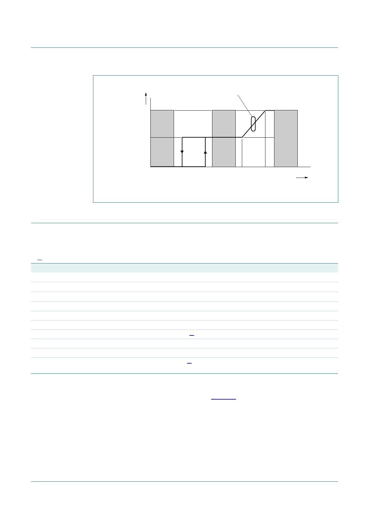
[5] The transition between Standby and Mute modes has hysteresis, while the slope of the transition between Mute and Operating modes is
determined by the time-constant of the RC network on pin MODE; see Figure 8.
[6] DC output offset voltage is gradually applied to the output during the transition between Mute and Operating modes. The slope caused
by any DC output offset is determined by the time-constant of the RC network on pin MODE.
[7] At a junction temperature of approximately T
act(th_fold)
5 °C, gain reduction commences and at a junction temperature of approximately
T
act(th_prot)
, the amplifier switches off.
Table 8. Static characteristics
V
P
[1]
=
±
30 V; f
osc
= 345 kHz; T
amb
= 25
°
C; unless otherwise specified.
Symbol Parameter Conditions Min Typ Max Unit
Supply
V
P
supply voltage Operating mode
[2]
±12.5 ±30 ±32.5 V
V
P(ovp)
overvoltage protection supply voltage Standby, Mute modes;
V
DD
V
SS
65 - 70 V
V
P(uvp)
undervoltage protection supply voltage V
DD
V
SS
20 - 25 V
V
P(ubp)
unbalance protection supply voltage
[3]
-33-%
I
q(tot)
total quiescent current Operating mode; no load; no
filter; no RC-snubber network
connected
- 5075mA
I
stb
standby current measured at 30 V - 480 650 µA
Mode select input; pin MODE
V
MODE
voltage on pin MODE referenced to SGND
[4]
0- 6V
Standby mode
[4][5]
0 - 0.8 V
Mute mode
[4][5]
2.2 - 3.0 V
Operating mode
[4][5]
4.2 - 6 V
I
I
input current V
I
= 5.5 V - 110 150 µA
Audio inputs; pins IN1M, IN1P, IN2P and IN2M
V
I
input voltage DC input
[4]
-0-V
Amplifier outputs; pins OUT1 and OUT2
V
O(offset)
output offset voltage SE; Mute mode - - ±25 mV
SE; Operating mode
[6]
--±150 mV
BTL; Mute mode - - ±30 mV
BTL; Operating mode
[6]
--±210 mV
Stabilizer output; pin STABI
V
O(STABI)
output voltage on pin STABI Mute and Operating modes;
with respect to VSSD
9.3 9.8 10.3 V
Temperature protection
T
act(th_prot)
thermal protection activation
temperature
- 154 - °C
T
act(th_fold)
thermal foldback activation
temperature
closed loop SE voltage gain
reduced with 6 dB
[7]
- 153 - °C
TDA8920C_2 © NXP B.V. 2009. All rights reserved.
Product data sheet Rev. 02 — 11 June 2009 14 of 39
NXP Semiconductors
TDA8920C
2 × 110 W class-D power amplifier
12. Dynamic characteristics
12.1 Switching characteristics
[1] V
P
is the supply voltage on pins VDDP1, VDDP2 and VDDA.
[2] When using an external oscillator, the frequency f
track
(500 kHz minimum, 900 kHz maximum) will result in a PWM frequency f
osc
(250 kHz minimum, 450 kHz maximum) due to the internal clock divider; see Section 8.2.
[3] When t
r(i)
> 100 ns, the output noise floor will increase.
Fig 8. Behavior of mode selection pin MODE
Standby Mute On
5.5
coa021
V
MODE
(V)
4.23.02.20.80
V
O
(V)
V
O(offset)(mute)
V
O(offset)(on)
slope is directly related to the time-constant
of the RC network on the MODE pin
Table 9. Dynamic characteristics
V
P
[1]
=
±
30 V; T
amb
= 25
°
C; unless otherwise specified.
Symbol Parameter Conditions Min Typ Max Unit
Internal oscillator
f
osc(typ)
typical oscillator frequency R
OSC
= 30.0 k 290 345 365 kHz
f
osc
oscillator frequency 250 - 450 kHz
External oscillator input or frequency tracking; pin OSC
V
OSC
voltage on pin OSC HIGH-level SGND + 4.5 SGND + 5 SGND + 6 V
V
trip
trip voltage - SGND + 2.5 - V
f
track
tracking frequency
[2]
500 - 900 kHz
Z
i
input impedance 1 - - M
C
i
input capacitance - - 15 pF
t
r(i)
input rise time from SGND + 0 V to
SGND + 5 V
[3]
- - 100 ns
TDA8920C_2 © NXP B.V. 2009. All rights reserved.
Product data sheet Rev. 02 — 11 June 2009 15 of 39
NXP Semiconductors
TDA8920C
2 × 110 W class-D power amplifier
12.2 Stereo SE configuration characteristics
[1] R
sL
is the series resistance of the low-pass LC filter inductor used in the application.
[2] Output power is measured indirectly; based on R
DSon
measurement; see Section 13.3.
[3] THD measured between 22 Hz and 20 kHz, using AES17 20 kHz brick wall filter; max. limit is guaranteed but may not be 100 % tested.
[4] V
ripple
= V
ripple(max)
= 2 V (p-p); measured independently between VDDPn and SGND and between VSSPn and SGND.
[5] 22 Hz to 20 kHz, using AES17 20 kHz brick wall filter.
[6] 22 Hz to 20 kHz, using AES17 20 kHz brick wall filter.
[7] P
o
= 1 W; f
i
= 1 kHz.
[8] V
i
= V
i(max)
= 1 V (RMS); f
i
= 1 kHz.
[9] Leads and bond wires included.
Table 10. Dynamic characteristics
V
P
=
±
30 V; R
L
= 4
; f
i
= 1 kHz; f
osc
= 345 kHz; R
sL
[1]
< 0.1
; T
amb
= 25
°
C; unless otherwise specified.
Symbol Parameter Conditions Min Typ Max Unit
P
o
output power L = 22 µH; C
LC
= 680 nF; T
j
=85°C
[2]
THD = 0.5 %; R
L
= 4 -90-W
THD = 10 %; R
L
= 4 - 110 - W
THD = 10 %; V
P
= ±27 V - 90 - W
THD total harmonic distortion P
o
= 1 W; f
i
= 1 kHz
[3]
- 0.05 - %
P
o
= 1 W; f
i
= 6 kHz
[3]
- 0.05 - %
G
v(cl)
closed-loop voltage gain 29 30 31 dB
SVRR supply voltage ripple rejection between pins VDDPn and SGND
Operating mode; f
i
= 100 Hz
[4]
-90-dB
Operating mode; f
i
= 1 kHz
[4]
-70-dB
Mute mode; f
i
= 100 Hz
[4]
-75-dB
Standby mode; f
i
= 100 Hz
[4]
- 120 - dB
between pins VSSPn and SGND
Operating mode; f
i
= 100 Hz
[4]
-80-dB
Operating mode; f
i
= 1 kHz
[4]
-60-dB
Mute mode; f
i
= 100 Hz
[4]
-80-dB
Standby mode; f
i
= 100 Hz
[4]
- 115 - dB
Z
i
input impedance between one of the input pins and
SGND
45 63 - k
V
n(o)
output noise voltage Operating mode; R
s
=0
[5]
- 160 - µV
Mute mode
[6]
-85-µV
α
cs
channel separation
[7]
-70-dB
|∆G
v
| voltage gain difference - - 1 dB
α
mute
mute attenuation f
i
= 1 kHz; V
i
= 2 V (RMS)
[8]
-75-dB
CMRR common mode rejection ratio V
i(CM)
= 1 V (RMS) - 75 - dB
η
po
output power efficiency SE, R
L
= 4 -88-%
SE, R
L
= 6 -90-%
BTL, R
L
= 8 -88-%
R
DSon(hs)
high-side drain-source on-state resistance
[9]
- 200 - m
R
DSon(ls)
low-side drain-source on-state resistance
[9]
- 190 - m

TDA8920CJ/N1,112

Mfr. #:
Manufacturer:
NXP Semiconductors
Description:
Audio Amplifiers Audio Amp Speaker 1CH Mono/2-CH Stereo
Lifecycle:
New from this manufacturer.
Delivery:
DHL FedEx Ups TNT EMS
Payment:
T/T Paypal Visa MoneyGram Western Union

Products related to this Datasheet