TDA8920C_2 © NXP B.V. 2009. All rights reserved.
Product data sheet Rev. 02 — 11 June 2009 7 of 39
NXP Semiconductors
TDA8920C
2 × 110 W class-D power amplifier
To ensure the coupling capacitors at the inputs (C
IN
in Figure 10) are fully charged before
the outputs start switching, a delay is inserted during the transition from Mute to Operating
mode. An overview of the start-up timing is provided in Figure 5. For proper switch-off, the
MODE pin should be forced LOW at least 100 ms before the supply lines (V
DDA
and V
SSA
)
drop below 12.5 V.
(1) First
1
4
pulse down.
Upper diagram: When switching from Standby to Mute, there is a delay of approximately 100 ms
before the output starts switching. The audio signal will become available once V
MODE
reaches the
Operating mode level (see Table 8), but not earlier than 150 ms after switching to Mute. To start-up
pop noise-free, it is recommended that the time constant applied to pin MODE be at least 350 ms
for the transition between Mute and Operating modes.
Lower diagram: When switching directly from Standby to Operating mode, there is a delay of
100 ms before the outputs start switching. The audio signal becomes available after a second
delay of 50 ms. To start-up pop noise-free, it is recommended that the time-constant applied to pin
MODE be at least 500 ms for the transition between Standby and Operating modes.
Fig 5. Timing on mode selection input pin MODE
2.2 V < V
MODE
< 3 V
audio output
operating
standby
mute
50 %
duty cycle
> 4.2 V
0 V (SGND)
time
001aah657
V
MODE
100 ms
50 ms
modulated PWM
> 350 ms
2.2 V < V
MODE
< 3 V
audio output
operating
standby
mute
50 %
duty cycle
> 4.2 V
0 V (SGND)
time
V
MODE
100 ms
50 ms
modulated PWM
> 350 ms
(1)
(1)
TDA8920C_2 © NXP B.V. 2009. All rights reserved.
Product data sheet Rev. 02 — 11 June 2009 8 of 39
NXP Semiconductors
TDA8920C
2 × 110 W class-D power amplifier
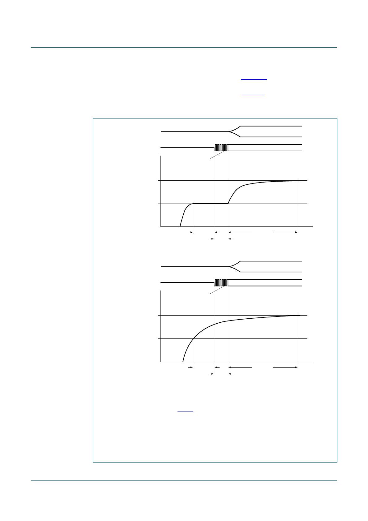
8.2 Pulse-width modulation frequency
The amplifier output signal is a PWM signal with a typical carrier frequency of between
250 kHz and 450 kHz. A 2nd-order LC demodulation filter on the output is used to convert
the PWM signal into an analog audio signal. The carrier frequency is determined by an
external resistor, R
OSC
, connected between pins OSC and VSSA. The optimal carrier
frequency setting is between 250 kHz and 450 kHz.
The carrier frequency is set to 345 kHz by connecting an external 30 kresistor between
pins OSC and VSSA. See Table 9 on page 14 for more details.
If two or more class-D amplifiers are used in the same audio application, it is
recommended that an external clock circuit be used with all devices (see Section 13.4).
This will ensure that they operate at the same switching frequency, thus avoiding beat
tones (if the switching frequencies are different, audible interference known as ‘beat tones’
can be generated)
8.3 Protection
The following protection circuits are incorporated into the TDA8920C:
Thermal protection:
Thermal FoldBack (TFB)
OverTemperature Protection (OTP)
OverCurrent Protection (OCP)
Window Protection (WP)
Supply voltage protection:
UnderVoltage Protection (UVP)
OverVoltage Protection (OVP)
UnBalance Protection (UBP)
How the device reacts to a fault conditions depends on which protection circuit has been
activated.
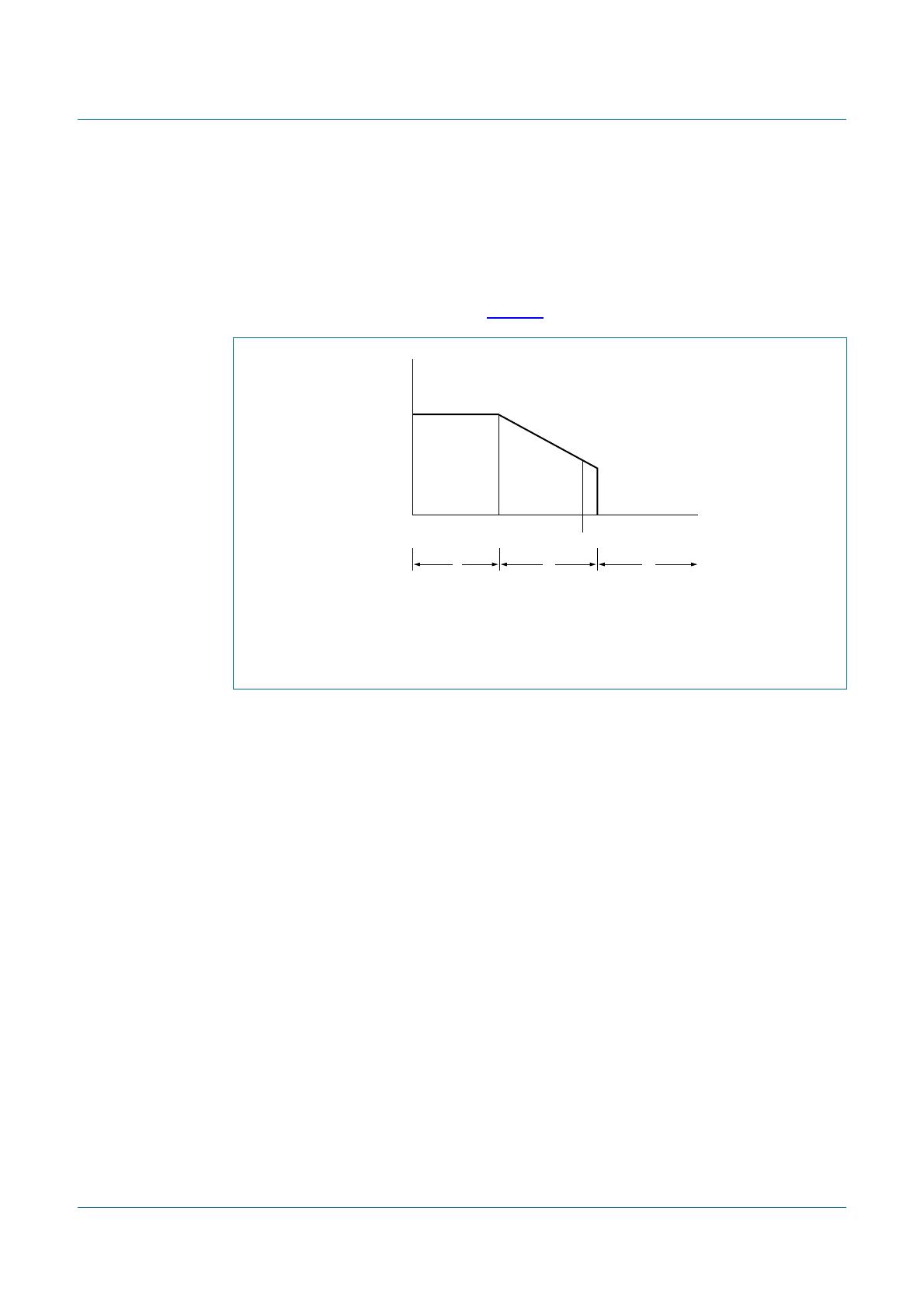
8.3.1 Thermal protection
The TDA8920C employes an advanced thermal protection strategy. A TFB function
gradually reduces the output power within a defined temperature range. If the temperature
continues to rise, OTP is activated to shut down the device completely.
8.3.1.1 Thermal FoldBack (TFB)
If the junction temperature (T
j
) exceeds the thermal foldback activation threshold, the gain
is gradually reduced. This reduces the output signal amplitude and the power dissipation,
eventually stabilizing the temperature.
TFB is specified at the thermal foldback activation temperature T
act(th_fold)
where the
closed-loop voltage gain is reduced by 6 dB. The TFB range is:
T
act(th_fold)
5 °C < T
act(th_fold)
< T
act(th_prot)
The value of T
act(th_fold)
for the TDA8920C is approximately 153 °C; see Table 8 for more
details.
TDA8920C_2 © NXP B.V. 2009. All rights reserved.
Product data sheet Rev. 02 — 11 June 2009 9 of 39
NXP Semiconductors
TDA8920C
2 × 110 W class-D power amplifier
8.3.1.2 OverTemperature Protection (OTP)
If TFB fails to stabilize the temperature and the junction temperature continues to rise, the
amplifier will shut down as soon as the temperature reaches the thermal protection
activation threshold, T
act(th_prot)
. The amplifier will resume switching approximately 100 ms
after the temperature drops below T
act(th_prot)
.
The thermal behavior is illustrated in Figure 6.
8.3.2 OverCurrent Protection (OCP)
In order to guarantee the robustness of the TDA8920C, the maximum output current that
can be delivered at the output stages is limited. OCP is built in for each output power
switch.
OCP is activated when the current in one of the power transistors exceeds the OCP
threshold (I
ORM
= 9.2 A) due, for example, to a short-circuit to a supply line or across the
load.
The TDA8920C amplifier distinguishes between low-ohmic short-circuit conditions and
other overcurrent conditions such as a dynamic impedance drop at the loudspeaker. The
impedance threshold (Z
th
) depends on the supply voltage.
How the amplifier reacts to a short circuit depends on the short-circuit impedance:
Short-circuit impedance > Z
th
: the amplifier limits the maximum output current to I
ORM
but the amplifier does not shut down the PWM outputs. Effectively, this results in a
clipped output signal across the load (behavior very similar to voltage clipping).
Short-circuit impedance < Z
th
: the amplifier limits the maximum output current to I
ORM
and at the same time discharges the capacitor on pin PROT. When C
PROT
is fully
discharged, the amplifier shuts down completely and an internal timer is started.
The value of the protection capacitor (C
PROT
) connected to pin PROT can be between
10 pF and 220 pF (typically 47 pF). While OCP is activated, an internal current source is
enabled that will discharge C
PROT
.
(1) Duty cycle of PWM output modulated according to the audio input signal.
(2) Duty cycle of PWM output reduced due to TFB.
(3) Amplifier is switched off due to OTP.
Fig 6. Behavior of TFB and OTP
001aah656
(T
act(th_fold)
5°C)
T
act(th_fold)
T
j
(°C) T
act(th_prot)
Gain
(dB)
30 dB
24 dB
0 dB
12 3

TDA8920CJ/N1,112

Mfr. #:
Manufacturer:
NXP Semiconductors
Description:
Audio Amplifiers Audio Amp Speaker 1CH Mono/2-CH Stereo
Lifecycle:
New from this manufacturer.
Delivery:
DHL FedEx Ups TNT EMS
Payment:
T/T Paypal Visa MoneyGram Western Union

Products related to this Datasheet