Rev. 1.3 9/11 Copyright © 2011 by Silicon Laboratories Si3453
QUAD HIGH-VOLTAGE PORT CONTROLLER
FOR POE AND POE+ PSES
Features
Applications
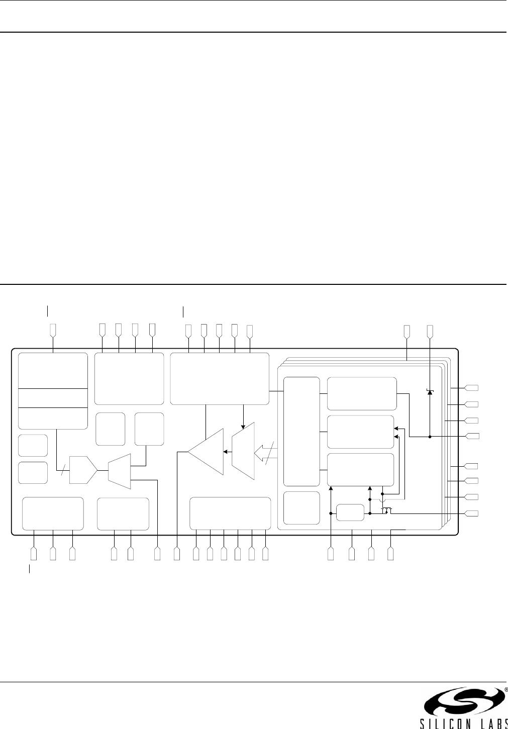
Each Si3453 high-voltage port
controller supports four PSE power
interfaces
Programmable current limits for PoE
(15.4 W), PoE+ (30 W), and
proprietary systems (up to 40 W) per
port
I
2
C interface requires no external
MCU for easy, low-cost management
of 4 to 48 ports by the host system
Unique mixed-signal IC high-voltage
component integration simplifies
design, lowers power dissipation,
minimizes external BOM, and
reduces PCB footprint
Internal low-R
ON
power FETs with
current-sense circuitry
Integrated transient voltage surge
suppressors
DC disconnect sensing method
Programmable architecture supports
IEEE 802.3af (PoE) and IEEE
802.3at (PoE+) PSEs
Programmable current limits for
PoE (350 mA) and PoE+
(600 mA), and custom limits to
850 mA
Per-port current and voltage
monitoring for sophisticated power
management and control
Power policing mode
Robust multi-point detection
Supports 1-Event and 2-Event
classification algorithms
Comprehensive, robust, fault-
protection circuitry
Supply undervoltage lockout
(UVLO)
Output current limit and short-
circuit protection
Foldback current limiting
Dual-threshold thermal overload
protection
Fault source reporting for
intelligent port management
Industrial (–40 to 85 °C) operating
temperature
Compact, 6×6 mm
2
, 40-pin QFN
RoHS-compliant package
Power over Ethernet Endpoint
switches and Midspans for IEEE Std
802.3af and 802.3at
Supports high-power PDs, such as:
Pan/Tilt/Zoom security cameras
802.11n WAPs
Multi-band, multi-radio WAPs
Security and RFID systems
Industrial automation systems
Networked audio
IP Phone Systems and iPBXs
Metropolitan area networked WAPs,
cameras, and sensors
WiMAX ASN/BTS and CPE/ODU
systems
Ordering Information:
See page 31.
Pin Assignments
40-pin QFN
See "9. Pin Descriptions" on page 28.
VEE
VEE1
AIN
RBIAS
VREF
AGND
AOUT
1
2
3
4
5
6
7
AGND
8
DGND
VDD
AD1
AD3
AD0
AD2
AD2
30
29
28
27
26
25
24
VOUT4
NC
SDA
NC
DET4
SCL
GND34
11
12
13
14
15
16
17
DET3
18
VDD
19
39
38
37
36
35
34
33
VOUT1
INT
DET1
AD0
RST
GND12
AD1
DET2
VEE4
10
NC
9
VEE3
22
RST
23
AD3
21
VOUT3
20
32
VOUT2
31
VEE2
Si3453
(Top View)
40
Si3453
Si3453
2 Rev. 1.3
Description
When connected directly to the host system or configured in Auto mode, each Si3453 high-voltage port controller
provides all of the critical circuitry and sophisticated power measurement functionality for the high-voltage
interfaces of four complete PSE ports. The Si3453 fully integrates robust, low-R
ON
(0.3 typical) power MOSFET
switches, low-power dissipation current sensing circuitry, and transient voltage surge suppression devices.
The on-chip current sense circuitry and power MOSFETs provide programmable scaling of current limits to match
either PoE (350 mA, 15.4 W), PoE+ (600 mA, 30 W), and extended (800 mA, 40 W) power requirements on a per-
port basis. Designed for use in Endpoint PSE (e.g., Ethernet switches) or Midspan PSE (e.g., inline power
injectors) applications, each Si3453 also performs the IEEE-required powered device (PD) detection, classification,
and disconnect functionality.
The flexible architecture enables powered device disconnect detection using a dc disconnect sensing algorithm.
Also provided are multi-point detection algorithms and per-port current and voltage monitoring.
Intelligent protection circuitry includes power supply undervoltage lockout (UVLO), port output current limiting and
short-circuit protection, thermal overload sensing and port shutdown, and transient voltage surge suppressors
capable of protecting the Si3453 from a variety of harsh surge events seen on the RJ-45 interface.
To maximize system design flexibility and minimize cost, each Si3453 connects directly to a system host controller
through an I
2
C serial interface, eliminating the need for an external MCU. The Si3453 can be set to one of 12
unique addresses, allowing control of up to 48 ports on a single I
2
C bus.
Functional Block Diagram
PER PORT ANALOG
AD2
AD1
AD3
HV SPI
&
Port
Control
VEE1
VOUT1
AOUT
Gate Control,
Current Limit
& Foldback
Detection
&
Classification
DC Disconnect
Channel
Mode
&
Limit
Control
VREF & Central Bias
MEAS.
MUX
PGA
DET4
VOUT2
VOUT3
DET3
DET2
GND12
AGND
VDD
VEE3
Thermal
Prot.
RBIAS
AD0
VEE2
VEE4
DET1
VOUT4
Current
Sense
VREF
VEE
DGND
AMUX
10b
ADC
Temp
Sensor
AIN
LV SPI
AD1
AD0
AD2
AD3
MCU Core
& PSE FSM
256 Byte SRAM
8 kByte EPROM
I2C
RST
PLL
Voltage
Regulator
& Monitor
VDD
AGND
POR
WDT
INT
GND34
RST
SDA
SCL
Si3453
Rev. 1.3 3
TABLE OF CONTENTS
Section Page
1. Electrical Specifications . . . . . . . . . . . . . . . . . . . . . . . . . . . . . . . . . . . . . . . . . . . . . . . . . . .4
2. PSE System-Level Diagrams . . . . . . . . . . . . . . . . . . . . . . . . . . . . . . . . . . . . . . . . . . . . . . .11
3. PSE Application Diagrams . . . . . . . . . . . . . . . . . . . . . . . . . . . . . . . . . . . . . . . . . . . . . . . .11
4. Functional Description . . . . . . . . . . . . . . . . . . . . . . . . . . . . . . . . . . . . . . . . . . . . . . . . . . .12
4.1. Detection . . . . . . . . . . . . . . . . . . . . . . . . . . . . . . . . . . . . . . . . . . . . . . . . . . . . . . . . . .12
4.2. Classification . . . . . . . . . . . . . . . . . . . . . . . . . . . . . . . . . . . . . . . . . . . . . . . . . . . . . . .13
4.3. Port Turn-On and Power FETs . . . . . . . . . . . . . . . . . . . . . . . . . . . . . . . . . . . . . . . . .13
4.4. Disconnect Detection . . . . . . . . . . . . . . . . . . . . . . . . . . . . . . . . . . . . . . . . . . . . . . . .14
4.5. Transient Voltage Surge Suppression . . . . . . . . . . . . . . . . . . . . . . . . . . . . . . . . . . .14
4.6. Temperature Sense . . . . . . . . . . . . . . . . . . . . . . . . . . . . . . . . . . . . . . . . . . . . . . . . .14
4.7. Port Measurement and Monitoring . . . . . . . . . . . . . . . . . . . . . . . . . . . . . . . . . . . . . .14
4.8. SMBus/I
2
C Interface Description . . . . . . . . . . . . . . . . . . . . . . . . . . . . . . . . . . . . . . .15
5. Register Interface . . . . . . . . . . . . . . . . . . . . . . . . . . . . . . . . . . . . . . . . . . . . . . . . . . . . . . . .17
5.1. Interrupt (Registers 0x00–0x01) . . . . . . . . . . . . . . . . . . . . . . . . . . . . . . . . . . . . . . . .17
5.2. Port Event (Registers 0x02–0x05) . . . . . . . . . . . . . . . . . . . . . . . . . . . . . . . . . . . . . .17
5.3. Port Status (Registers 0x06–0x09) . . . . . . . . . . . . . . . . . . . . . . . . . . . . . . . . . . . . . .17
5.4. Port Configuration (Registers 0x0A–0x11) . . . . . . . . . . . . . . . . . . . . . . . . . . . . . . . .18
5.5. Command and Return Registers (Registers 0x12–0x1C) . . . . . . . . . . . . . . . . . . . . .19
5.6. Device Status Register (0x1D) . . . . . . . . . . . . . . . . . . . . . . . . . . . . . . . . . . . . . . . . .19
6. Operational Notes . . . . . . . . . . . . . . . . . . . . . . . . . . . . . . . . . . . . . . . . . . . . . . . . . . . . . . .25
6.1. Port Turn On . . . . . . . . . . . . . . . . . . . . . . . . . . . . . . . . . . . . . . . . . . . . . . . . . . . . . . .25
6.2. Changing the Interrupt Mask . . . . . . . . . . . . . . . . . . . . . . . . . . . . . . . . . . . . . . . . . . .25
6.3. Port Voltage and Current Measurements . . . . . . . . . . . . . . . . . . . . . . . . . . . . . . . . .25
7. PCB Layout Guidelines . . . . . . . . . . . . . . . . . . . . . . . . . . . . . . . . . . . . . . . . . . . . . . . . . . .26
8. Firmware Release Notes . . . . . . . . . . . . . . . . . . . . . . . . . . . . . . . . . . . . . . . . . . . . . . . . . .27
8.1. I
2
C Address ACK . . . . . . . . . . . . . . . . . . . . . . . . . . . . . . . . . . . . . . . . . . . . . . . . . . .27
9. Pin Descriptions . . . . . . . . . . . . . . . . . . . . . . . . . . . . . . . . . . . . . . . . . . . . . . . . . . . . . . . . .28
10. Package Outline: 40-Pin QFN . . . . . . . . . . . . . . . . . . . . . . . . . . . . . . . . . . . . . . . . . . . . .31
11. Recommended PCB Footprint . . . . . . . . . . . . . . . . . . . . . . . . . . . . . . . . . . . . . . . . . . . .32
12. Ordering Guide . . . . . . . . . . . . . . . . . . . . . . . . . . . . . . . . . . . . . . . . . . . . . . . . . . . . . . . . .34
12.1. Evaluation Kits and Reference Designs . . . . . . . . . . . . . . . . . . . . . . . . . . . . . . . . .34
13. Device Marking Diagram . . . . . . . . . . . . . . . . . . . . . . . . . . . . . . . . . . . . . . . . . . . . . . . . .35
Document Change List . . . . . . . . . . . . . . . . . . . . . . . . . . . . . . . . . . . . . . . . . . . . . . . . . . . . .36
Contact Information . . . . . . . . . . . . . . . . . . . . . . . . . . . . . . . . . . . . . . . . . . . . . . . . . . . . . . . .38

SI3453B-B02-GM

Mfr. #:
Manufacturer:
Silicon Labs
Description:
Hot Swap Voltage Controllers
Lifecycle:
New from this manufacturer.
Delivery:
DHL FedEx Ups TNT EMS
Payment:
T/T Paypal Visa MoneyGram Western Union