AD7705/AD7706
Rev. C | Page 19 of 44
CLOCK REGISTER (RS2, RS1, RS0 = 0, 1, 0); POWER-ON/RESET STATUS: 05 HEXADECIMAL
The clock register is an 8-bit register from which data can be read or to which data can be written.
Table 18 outlines the bit designations for the clock register.
Table 18. Clock Register
ZERO (0) ZERO (0) ZERO (0) CLKDIS (0) CLKDIV (0) CLK (1) FS1 (0) FS0 (1)
Table 19. Clock Register Description
Register Description
ZERO
Zero. A zero must be written to these bits to ensure correct operation of the AD7705/AD7706. Failure to do so might result in
unspecified operation of the device.
CLKDIS
Master Clock Disable Bit. Logic 1 in this bit disables the master clock, preventing it from appearing at the MCLK OUT pin. When
disabled, the MCLK OUT pin is forced low. This feature allows the user the flexibility of either using the MCLK OUT as a clock
source for other devices in the system, or turning off the MCLK OUT as a power-saving feature. When using an external master
clock on the MCLK IN pin, the AD7705/AD7706 continue to have internal clocks and convert normally with the CLKDIS bit
active. When using a crystal oscillator or ceramic resonator across Pin MCLK IN and Pin MCLK OUT, the AD7705/AD7706 clocks
are stopped, and no conversions take place when the CLKDIS bit is active.
CLKDIV
Clock Divider Bit. With this bit at Logic 1, the clock frequency appearing at the MCLK IN pin is divided by 2 before being used
internally by the AD7705/AD7706. For example, when this bit is set to Logic 1, the user can operate with a 4.9152 MHz crystal
between Pin MCLK IN and Pin MCLK OUT, and internally the part operates with the specified 2.4576 MHz. With this bit at
Logic 0, the clock frequency appearing at the MCLK IN pin is the frequency used internally by the part.
CLK
Clock Bit. This bit should be set in accordance with the operating frequency of the AD7705/AD7706. If the device has a master
clock frequency of 2.4576 MHz (CLKDIV = 0) or 4.9152 MHz (CLKDIV = 1), this bit should be set to Logic 1. If the device has a
master clock frequency of 1 MHz (CLKDIV = 0) or 2 MHz (CLKDIV = 1), this bit should be set to Logic 0. This bit sets up the
appropriate scaling currents for a given operating frequency and, together with FS1 and FS0, chooses the output update rate
for the device. If this bit is not set correctly for the master clock frequency of the device, the AD7705/AD7706 might not
operate to specification.
FS1, FS0
Filter Selection Bits. Along with the CLK bit, FS1 and FS0 determine the output update rate, the filters first notch, and the −3 dB
frequency, as outlined in
Table 20. The on-chip digital filter provides a sinc
3
(or (sinx/x)
3
) filter response. In association with the
gain selection, it also determines the output noise of the device. Changing the filter notch frequency, as well as the selected gain,
impacts resolution. Table 5 through Table 8 show the effects of filter notch frequency and gain on the output noise and effective
resolution of the part. The output data rate, or effective conversion time, for the device is equal to the frequency selected for
the first notch of the filter. For example, if the first notch of the filter is selected at 50 Hz, a new word is available at a 50 Hz output
rate, or every 20 ms. If the first notch is at 500 Hz, a new word is available every 2 ms. A calibration should be initiated when
any of these bits are changed. The settling time of the filter to a full-scale step input is worst case 4 × 1/(output data rate). For
example, with the filter-first notch at 50 Hz, the settling time of the filter to a full-scale step input is 80 ms maximum. If the first
notch is at 500 Hz, the settling time is 8 ms maximum. This settling time can be reduced to 3 × 1/(output data rate) by
synchronizing the step input change with a reset of the digital filter. In other words, if the step input takes place with the
FSYNC bit high, the settling time is 3 × 1/(output data rate) from the time when the FSYNC bit returns low. The −3 dB
frequency is determined by the programmed first notch frequency according to the relationship:
frequencynotchfirstfilterfrequencyfilter -262.0dB3 ×=
Table 20. Output Update Rates
CLK
1
FS1 FS0 Output Update Rate −3 dB Filter Cutoff
0 0 0 20 Hz 5.24 Hz
0 0 1 25 Hz 6.55 Hz
0 1 0 100 Hz 26.2 Hz
0 1 1 200 Hz 52.4 Hz
1 0 0 50 Hz 13.1 Hz
1 0 1 60 Hz 15.7 Hz
1 1 0 250 Hz 65.5 Hz
1 1 1 500 Hz 131 Hz
1
Assumes correct clock frequency on MCLK IN pin with the CLKDIV bit set appropriately.
AD7705/AD7706
Rev. C | Page 20 of 44
DATA REGISTER (RS2, RS1, RS0 = 0, 1, 1)
The data register is a 16-bit, read-only register that contains the
most up-to-date conversion result from the AD7705/AD7706. If
the communication register sets up the part for a write
operation to this register, a write operation must take place to
return the part to its default state. However, the 16 bits of data
written to the part will be ignored by the AD7705/AD7706.
TEST REGISTER (RS2, RS1, RS0 = 1, 0, 0);
POWER-ON/RESET STATUS: 00 HEXADECIMAL
The part contains a test register that is used when testing the
device. The user is advised not to change the status of any of the
bits in this register from the default (power-on or reset) status
of all 0s, because the part will be placed in one of its test modes
and will not operate correctly.
ZERO-SCALE CALIBRATION REGISTER
(RS2, RS1, RS0 = 1, 1, 0);
POWER-ON/RESET STATUS: 1F4000 HEXADECIMAL
The AD7705/AD7706 contain independent sets of zero-scale
registers, one for each of the input channels. Each register is a
24-bit read/write register; therefore, 24 bits of data must be
written, or no data is transferred to the register. This register is
used in conjunction with its associated full-scale register to
form a register pair. These register pairs are associated with
input channel pairs, as outlined in
Table 12 and Table 13.
While the part is set up to allow access to these registers over
the digital interface, the parts themselves can no longer access
the register coefficients to scale the output data correctly. As a
result, the first output data read from the part after accessing
the calibration registers (for either a read or write operation)
might contain incorrect data. In addition, a write to the
calibration register should not be attempted while a calibration
is in progress. These eventualities can be avoided by taking the
FSYNC bit in the mode register high before the calibration
register operation, and taking it low after the operation is
complete.
FULL-SCALE CALIBRATION REGISTER
(RS2, RS1, RS0 = 1, 1, 1);
POWER-ON/RESET STATUS: 5761AB HEXADECIMAL
The AD7705/AD7706 contain independent sets of full-scale
registers, one for each of the input channels. Each register is a
24-bit read/write register; therefore, 24 bits of data must be
written, or no data is transferred to the register. This register is
used in conjunction with its associated zero-scale register to
form a register pair. These register pairs are associated with
input channel pairs, as outlined in
Table 12 and Table 13.
While the part is set up to allow access to these registers over
the digital interface, the part itself can no longer access the
register coefficients to scale the output data correctly. As a
result, the first output data read from the part after accessing
the calibration registers (for either a read or write operation)
might contain incorrect data. In addition, a write to the
calibration register should not be attempted while a calibration
is in progress. These eventualities can be avoided by taking
FSYNC bit in the mode register high before the calibration
register operation, and taking it low after the operation is
complete.
Calibration Sequences
The AD7705/AD7706 contain a number of calibration options,
as previously outlined.
Table 21 summarizes the calibration
types, the operations involved, and the duration of the
operations. There are two methods for determining the end of a
calibration. The first is to monitor when
DRDY
returns low at
the end of the sequence. This technique not only indicates when
the sequence is complete, but also when the part has a valid new
sample in its data register. This valid new sample is the result of
a normal conversion that follows the calibration sequence. The
second method for determining when calibration is complete is
to monitor the MD1 and MD0 bits of the setup register. When
these bits return to 0 following a calibration command, the
calibration sequence is complete. This technique can indicate
the completion of a calibration earlier than the first method
can, but it cannot indicate when there is a valid new result in
the data register. The time that it takes the mode bits, MD1 and
MD0, to return to 0 represents the duration of the calibration.
The sequence when
DRDY
goes low includes a normal
conversion and a pipeline delay, t
P
, to scale the results of this
first conversion correctly. Note that t
P
never exceeds 2000 ×
t
CLKIN
. The time for both methods is shown in Table 21.
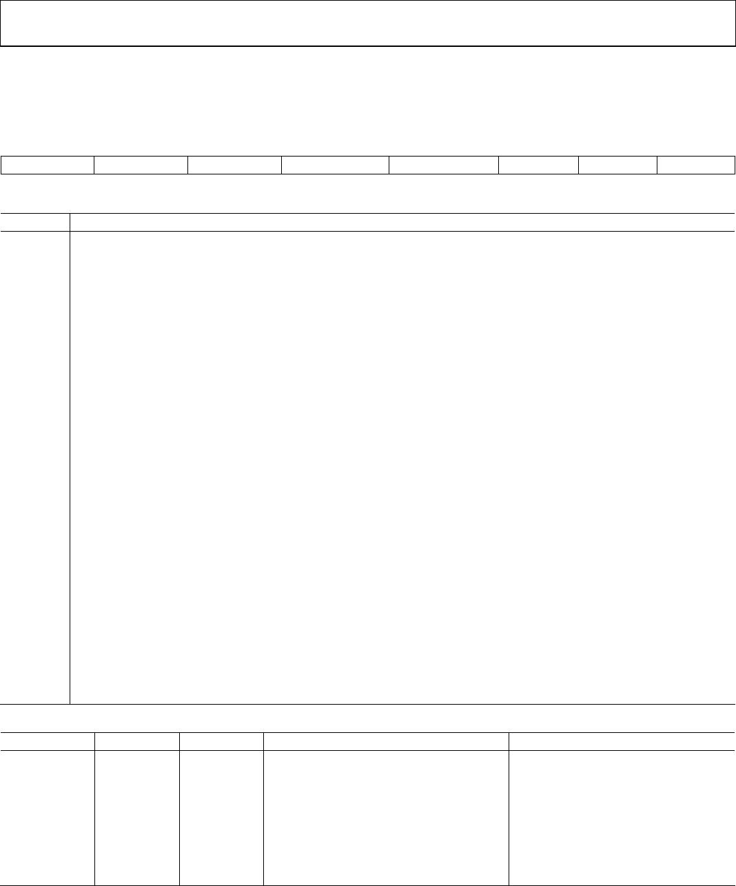
Table 21. Calibration Sequences
Calibration Type MD1, MD0 Calibration Sequence Duration of Mode Bits Duration of
DRDY
Self-Calibration 0, 1
Internal ZS calibration @ selected gain
+ internal FS calibration @ selected
gain
6 × 1/output rate 9 × 1/output rate + t
P
ZS System Calibration 1, 0 ZS calibration on AIN @ selected gain 3 × 1/output rate 4 × 1/output rate + t
P
FS System Calibration 1, 1 FS calibration on AIN @ selected gain 3 × 1/output rate 4 × 1/output rate + t
P
AD7705/AD7706
Rev. C | Page 21 of 44
CIRCUIT DESCRIPTION
The AD7705/AD7706 are Σ-Δ analog-to-digital converters (ADC)
with on-chip digital filtering, intended for the measurement of
wide, dynamic range, low frequency signals, such as those in
industrial-control or process-control applications. Each contains
a Σ-Δ (or charge-balancing) ADC, a calibration microcontroller
with on-chip static RAM, a clock oscillator, a digital filter, and a
bidirectional serial communication port. The parts consume only
320 μA of power supply current, making them ideal for battery-
powered or loop-powered instruments. These parts operate with
a supply voltage of 2.7 V to 3.3 V or 4.75 V to 5.25 V.
The AD7705 contains two programmable-gain, fully differential
analog input channels, and the AD7706 contains three pseudo
differential analog input channels. The selectable gains on these
inputs are 1, 2, 4, 8, 16, 32, 64, and 128, allowing the parts to accept
unipolar signals of 0 mV to 20 mV and 0 V to 2.5 V, or bipolar
signals in the range of ±20 mV to ±2.5 V when the reference input
voltage equals 2.5 V. With a reference voltage of 1.225 V, the input
ranges are from 0 mV to 10 mV and 0 V to 1.225 V in unipolar
mode, and from ±10 mV to ±1.225 V in bipolar mode. Note that
the bipolar ranges are with respect to AIN(−) on the AD7705,
and with respect to COMMON on the AD7706, but not with
respect to GND.
The input signal to the analog input is continuously sampled at a
rate determined by the frequency of the master clock, MCLK IN,
and the selected gain. A charge-balancing ADC (∑-Δ modulator)
converts the sampled signal into a digital pulse train whose duty
cycle contains the digital information. The programmable gain
function on the analog input is also incorporated in this Σ-Δ
modulator, with the input sampling frequency being modified
to provide higher gains. A sinc
3
, digital, low-pass filter processes
the output of the Σ-Δ modulator and updates the output register
at a rate determined by the first notch frequency of this filter.
The output data can be read from the serial port randomly or
periodically at any rate up to the output register update rate.
The frequency of the first notch of the digital filter ranges from
50 Hz to 500 Hz; therefore, the programmable range for the
−3 dB frequency is 13.1 Hz to 131 Hz. With a master clock
frequency of 1 MHz, the programmable range for this first
notch frequency is 20 Hz to 200 Hz, giving a programmable
range for the −3 dB frequency of 5.24 Hz to 52.4 Hz.
The AD7705 basic connection diagram is shown in
Figure 13.
It shows the AD7705 driven from an analog 5 V supply. An
AD780 or REF192 precision 2.5 V reference provides the reference
source for the part. On the digital side, the part is configured for
3-wire operation with
CS
tied to GND. A quartz crystal or ceramic
resonator provides the master clock source for the part. In most
cases, it is necessary to connect capacitors on the crystal or
resonator to ensure that it does not oscillate at overtones of its
fundamental operating frequency. The values of capacitors vary,
depending on the manufacturer’s specifications. The same setup
applies to the AD7706.
V
DD
ANALOG
5V SUPPLY
10μF
AIN1(+)
AIN1(–)
AIN2(+)
AIN2(–)
DIFFERENTIAL
ANALOG
INPUT
DIFFERENTIAL
ANALOG
INPUT
GND
REF IN(+)
REF IN(–)
10μF
V
IN
ANALOG 5V
SUPPLY
AD780/
REF192
V
OUT
GND
AD7705
DRDY
DATA READY
DOUT
RECEIVE (READ)
DIN
SERIAL DATA
SCLK
SERIAL CLOCK
RESET
5V
CS
MCLK IN
MCLK OUT
CRYSTAL OR
CERAMIC
RESONATOR
0.1μF
0.1μF
01166-013
Figure 13. AD7705 Basic Connection Diagram

AD7706BRZ

Mfr. #:
Manufacturer:
Analog Devices Inc.
Description:
Analog to Digital Converters - ADC 3V/5V 1mW 3-Ch Pseudo Diff 16-Bit
Lifecycle:
New from this manufacturer.
Delivery:
DHL FedEx Ups TNT EMS
Payment:
T/T Paypal Visa MoneyGram Western Union