LTC3300-1
6
33001fb
For more information www.linear.com/LTC3300-1
Note 1: Stresses beyond those listed under Absolute Maximum Ratings
may cause permanent damage to the device. Exposure to any Absolute
Maximum Rating condition for extended periods may affect device
reliability and lifetime.
Note 2: The LTC3300-1 is tested under pulsed load conditions such
that T
J
≈ T
A
. The LTC3300I-1 is guaranteed over the –40°C to 125°C
operating junction temperature range and the LTC3300H-1 is guaranteed
over the –40°C to 150°C operating junction temperature. High junction
temperatures degrade operating lifetimes; operating lifetime is derated
for junction temperatures greater than 125°C. Note that the maximum
ambient temperature consistent with these specifications is determined by
specific operating conditions in conjunction with board layout, the rated
package thermal impedance and other environmental factors. The junction
temperature (T
J
, in °C) is calculated from the ambient temperature
(T
A
, in °C) and power dissipation (P
D
, in Watts) according to the formula:
T
J
= T
A
+ (P
D
• θ
JA
)
where θ
JA
(in °C/W) is the package thermal impedance.
Note 3: When balancing more than one cell at a time, the individual cell
supply currents can be calculated from the values given in the table as
follows: First add the appropriate table entries cell by cell for the balancers
that are on. Second, for each additional balancer that is on, subtract 70µA
from the resultant sums for C1, C2, C3, C4, and C5, and 450µA from the
resultant sum for C6. For example, if all six balancers are on, the resultant
current for C1 is [250 – 70 + 70 + 70 + 70 + 70 – 5(70)]µA = 110µA and
for C6 is [560 + 560 + 560 + 560 + 560 + 740 – 5(450)]µA = 1290µA.
Note 4: Dynamic supply current is higher due to gate charge being
delivered at the switching frequency during active balancing. See Gate
Drivers/Gate Drive Comparators and Voltage Regulator in the Operation
section for more information on estimating these currents.
Note 5: The zero current sense voltages given in the table are DC
thresholds. The actual zero current sense voltage seen in application will
be closer to zero due to the slew rate of the winding current and the finite
delay of the current sense comparator.
Note 6: The mid-range value is the average of the minimum and maximum
readings within the group of six.
Note 7: This IC includes overtemperature protection intended to protect
the device during momentary overload conditions. The maximum junction
temperature may be exceeded when overtemperature protection is active.
Continuous operation above the specified maximum operating junction
temperature may result in device degradation or failure.
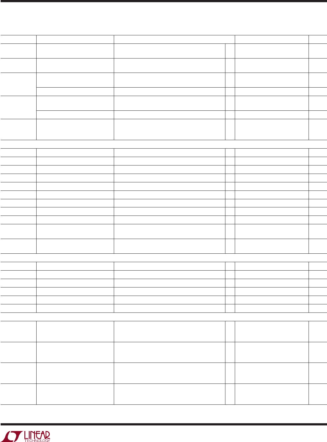
SYMBOL PARAMETER CONDITIONS MIN TYP MAX UNITS
V
OL
Digital Output Voltage Low Pin SDO, Sinking 500µA; V
MODE
= V
REG
; Read
l
0.3 V
I
OH
Digital Output Current High Pin SDO at 6V
l
100 nA
Current Mode Digital I/O Specifications
I
IL1
Digital Input Current Low Pin CSBI; V
MODE
= V
–
Pin SCKI; V
MODE
= V
–
Pin SDI, V
MODE
= V
–
, Write
Pin SDOI, TOS = V
–
, Read
l
l
l
l
–1500
–5
–5
0
–1250
–2.5
–2.5
2.5
–1000
0
0
5
µA
µA
µA
µA
I
IH1
Digital Input Current High Pin CSBI; V
MODE
= V
–
Pin SCKI; V
MODE
= V
–
Pin SDI, V
MODE
= V
–
, Write
Pin SDOI, TOS = V
–
, Read
l
l
l
l
–5
–1500
–1500
1000
–2.5
–1250
–1250
1250
0
–1000
–1000
1500
µA
µA
µA
µA
I
OH1
Digital Output Current High Pin CSBO; TOS = V
–
Pin SCKO; TOS = V
–
Pin SDOI, TOS = V
–
, Write
Pin SDI, V
MODE
= V
–
, Read
l
l
l
l
0
1000
1000
2.5
1250
1250
5
–1000
µA
µA
µA
µA
I
OL1
Digital Output Current Low Pin CSBO; TOS = V
–
Pin SCKO; TOS = V
–
Pin SDOI, TOS = V
–
, Write
Pin SDI, V
MODE
= V
–
, Read
l
l
l
l
1000
0
0
–5
1250
2.5
2.5
5
5
µA
µA
µA
µA
The l denotes the specifications which apply over the full operating
junction temperature range, otherwise specifications are at T
A
= 25°C. (Note 2) BOOST
+
= 25.2V, C6 = 21.6V, C5 = 18V, C4 = 14.4V,
C3 = 10.8V, C2 = 7.2V, C1 = 3.6V, V
–
= 0V, unless otherwise noted.
ELECTRICAL CHARACTERISTICS