PCA8546 All information provided in this document is subject to legal disclaimers. © NXP B.V. 2013. All rights reserved.
Product data sheet Rev. 1 — 13 November 2013 10 of 63
NXP Semiconductors
PCA8546
4 x 44 automotive LCD driver
With the following sequence, the PCA8546 can be set to a state of minimum power
consumption, called power-down mode.
Remarks:
It is necessary to run the power-down sequence before removing the supplies.
Depending on the application, care must be taken that no other signals are present at
the chip input or output pins when removing the supplies (see Section 10
). Otherwise
it may cause unwanted display artifacts. If an uncontrolled removal of the supply
happens, the PCA8546 does not get damaged.
Static voltages across the liquid crystal display can build up when the external LCD
supply voltage (V
LCD
) is on while the IC supply voltage is off, or the other way around.
This may cause unwanted display artifacts. To avoid such artifacts, V
LCD
and V
DD
must be applied or removed together.
Table 9. Effect of the power-down bit (PD)
Effect on function Mode settings Effect of setting PD
0 1
backplane output E = 1 normal function V
SS
segment output E = 1 normal function V
SS
internal oscillator OSC = 0, COE = 1 on off
OSCCLK pin OSC = 0, COE = 1 output of internal
oscillator frequency
V
DD
OSCCLK pin OSC = 1 input clock clock input, can be
logic 0, logic 1, or left
floating
Fig 6. Recommended power-down sequence
67$57
'LVDEOHGLVSOD\
E\VHWWLQJELW(
ORJLF
([WHUQDOFORFN
FDQEH
UHPRYHGQRZ
DDD
(QDEOHSRZHU
GRZQPRGH
ZLWK3' 
6723
PCA8546 All information provided in this document is subject to legal disclaimers. © NXP B.V. 2013. All rights reserved.
Product data sheet Rev. 1 — 13 November 2013 11 of 63
NXP Semiconductors
PCA8546
4 x 44 automotive LCD driver
A clock signal must always be supplied to the device when the display is active.
Removing the clock may freeze the LCD in a DC state, which is not suitable for the
liquid crystal. First disable the display and afterwards remove the clock signal.
8.1.3.4 Display enable
The display enable bit (E) is used to enable and disable the display. When the display is
disabled, all LCD outputs go to V
SS
. This function is implemented to ensure that no
voltage can be induced on the LCD outputs as it may lead to unwanted displays of
segments.
Recommended start-up sequences are found in Section 8.2.3
Remark: Display enable is not synchronized to an LCD frame boundary. Therefore using
this function to flash a display for prolonged periods is not recommended due to the
possible build-up of DC voltages on the display.
8.1.4 Command: oscillator-control
The oscillator-control command switches between internal and external oscillator and
enables or disables the pin OSCCLK. It is also defines the external frequency.
[1] Default value.
The bits OSC, COE, and EFR control the source and frequency of the clock used to
generate the LCD signals (see Figure 7
). Valid combinations are shown in Table 11 .
Table 10. Oscillator-control - oscillator control command bit description
Bit Symbol Value Description
7 to 3 - 00011 fixed value
2EFR external clock frequency applied on pin
OSCCLK
0
[1]
9.6 kHz
1 230 kHz
1COE clock output enable for pin OSCCLK
0
[1]
clock signal not available on pin OSCCLK;
pin OSCCLK is in 3-state
1 clock signal available on pin OSCCLK
0OSC oscillator source
0
[1]
internal oscillator running
1 external oscillator used;
pin OSCCLK becomes an input;
used in combination with EFR to determine
input frequency
PCA8546 All information provided in this document is subject to legal disclaimers. © NXP B.V. 2013. All rights reserved.
Product data sheet Rev. 1 — 13 November 2013 12 of 63
NXP Semiconductors
PCA8546
4 x 44 automotive LCD driver
8.1.4.1 Oscillator
The system is designed to operate from a 9.6 kHz or a 230 kHz clock. This clock can be
sourced internally or externally. The internal logic and LCD drive signals of the PCA8546
are timed either by the internal oscillator or from the clock externally supplied.
Internal clock: When the internal oscillator is used, all LCD signals are generated from it.
The oscillator runs at nominal 230 kHz. The relationship between this frequency and the
LCD frame frequency is detailed in Section 8.1.6
. Control over the internal oscillator is
made with the OSC bit (see Section 8.1.4
).
It is possible to make the internal oscillator signal available on pin OSCCLK by using the
oscillator-control command (see Table 10
) and configuring the clock output enable (COE)
bit. If not required, the pin OSCCLK should be left open or connected to V
SS
. At power-on
the signal at pin OSCCLK is disabled and pin OSCCLK is in 3-state.
Clock output is only valid when using the internal oscillator. The signal appears on the
OSCCLK pin.
An intermediate clock frequency is available at the OSCCLK pin. The duty cycle of this
clock varies with the chosen divide ratio.
(1) Can only be used with the internal oscillator (OSC = 0).
(2) Can only be used with an external oscillator (OSC = 1).
(3) Nominal value for divide factor q is 24; source clock is 230 kHz (see Section 8.1.6
).
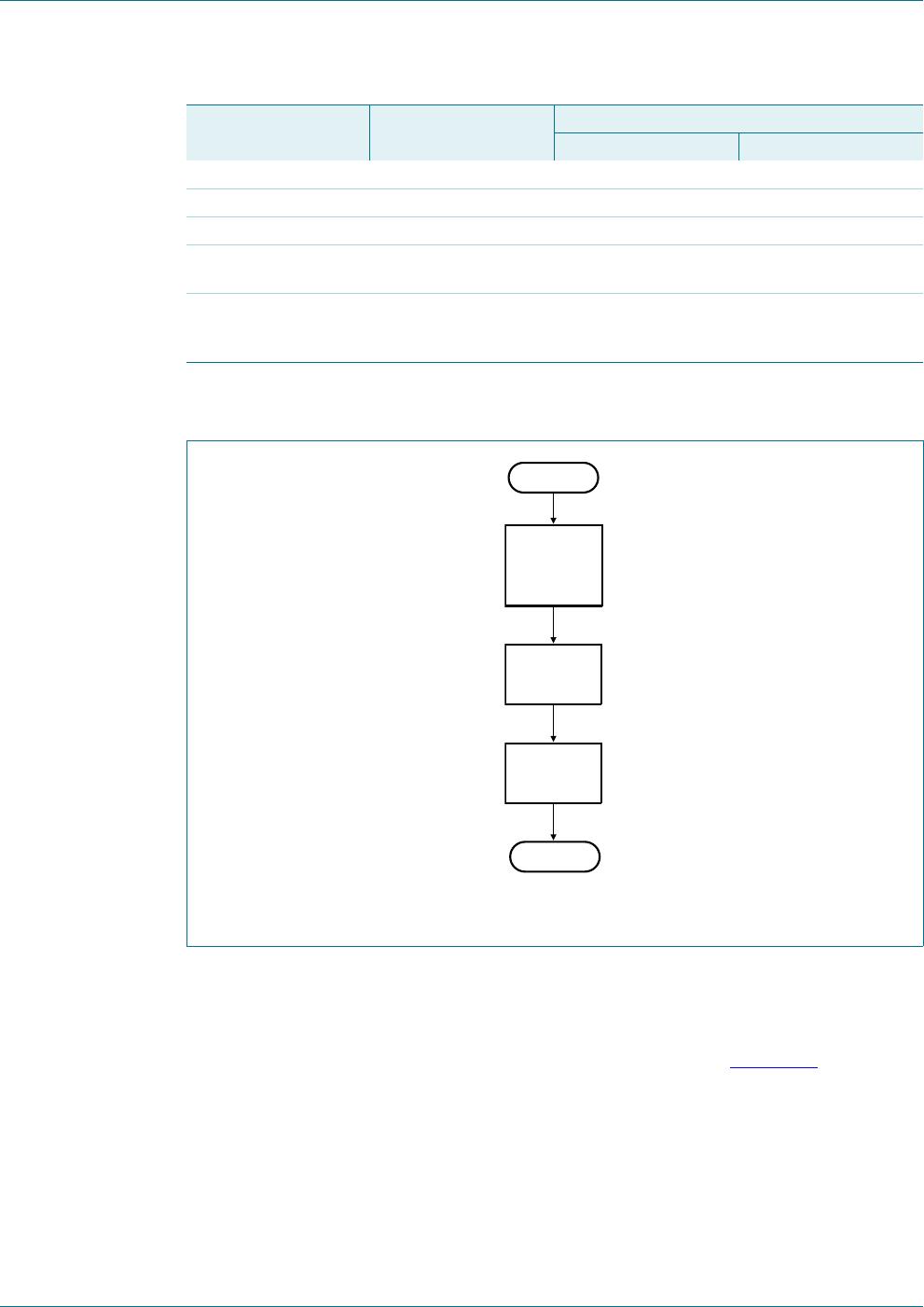
Fig 7. Oscillator selection
Table 11. Valid combinations of bits OSC, EFR, and COE
OSC COE EFR OSCCLK pin Clock source
0 0 not used inactive;
may be left floating
internal oscillator used
0 1 not used output of internal oscillator
frequency (prescaler)
internal oscillator used
1 not used 0 9.6 kHz input OSCCLK pin
1 not used 1 230 kHz input OSCCLK pin
Table 12. Typical use of bits OSC, EFR, and COE
Usage OSC COE EFR
LCD with internal oscillator 0 0 not used
LCD with external oscillator (230 kHz) 1 not used 1
LCD with external oscillator (9.6 kHz) 1 not used 0
,QWHUQDORVFLOODWRU
N+]
3URJUDPPDEOH
GLYLGHU
/&'ZDYHIRUP
JHQHUDWRU
DDD
26&&/.
SLQ
/&'IUDPHIUHTXHQF\
VHOHFWLRQT
()5
N+]
26&
&2(

PCA8546BTT/AJ

Mfr. #:
Manufacturer:
NXP Semiconductors
Description:
LCD Drivers PCA8546BTT/TSSOP56//A/REEL 13 Q1 NDP
Lifecycle:
New from this manufacturer.
Delivery:
DHL FedEx Ups TNT EMS
Payment:
T/T Paypal Visa MoneyGram Western Union

Products related to this Datasheet