PCA8546 All information provided in this document is subject to legal disclaimers. © NXP B.V. 2013. All rights reserved.
Product data sheet Rev. 1 — 13 November 2013 19 of 63
NXP Semiconductors
PCA8546
4 x 44 automotive LCD driver
Fig 9. Recommended start-up sequence when using the internal oscillator
67$57
3RZHURQ9
''
DQG9
/&'
WRJHWKHU
2SWLRQDOO\
WRJJOH
:DLWPLQLPXP
PV
6HQG
273UHIUHVK
6HW
PRGHVHWWLQJV%36DQG,19
ELDVPRGH
/&'IUDPHIUHTXHQF\
6HQGGLVSOD\
FRQWHQW
(QDEOH
WKHGLVSOD\
6723
DDD
6HQGLQLWLDOL]H
FRPPDQG
06%DQG/6%
5(6(7SLQ
PCA8546 All information provided in this document is subject to legal disclaimers. © NXP B.V. 2013. All rights reserved.
Product data sheet Rev. 1 — 13 November 2013 20 of 63
NXP Semiconductors
PCA8546
4 x 44 automotive LCD driver
8.3 Possible display configurations
The PCA8546 is a versatile peripheral device designed to interface between any
microcontroller to a wide variety of LCD segment or dot matrix displays (see Figure 10
). It
can drive multiplexed LCD with 4 backplanes and up to 44 segments.
[1] 7 segment display has 8 elements including the decimal point.
[2] 14 segment display has 16 elements including decimal point and accent dot.
The display configuration in Table 21 can be implemented in the typical systems shown in
Figure 11
and Figure 12.
Fig 10. Example of displays suitable for PCA8546
Table 21. Display configuration
Number of Digits/Characters Dot matrix/
Elements
Backplanes Segments Icons 7 segment
[1]
14 segment
[2]
4 44 176 22 11 176
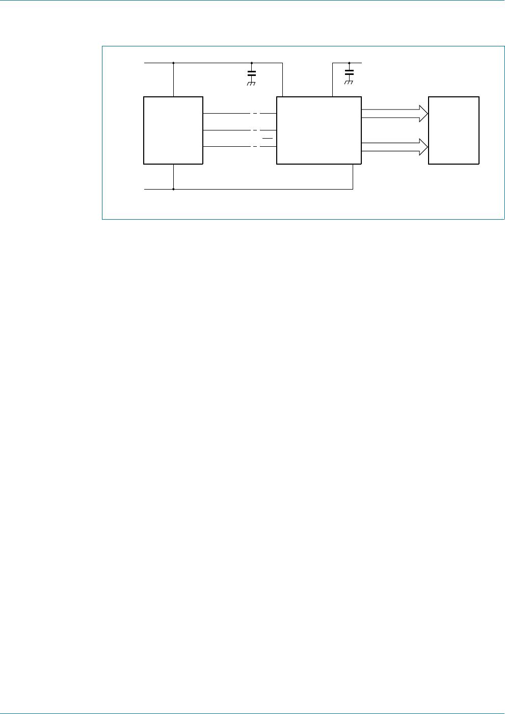
Fig 11. Typical system configuration for the I
2
C-bus
VHJPHQWZLWKGRW VHJPHQWZLWKGRWDQGDFFHQW
DDD
GRWPDWUL[
+267
0,&52
&21752//(5
5
W
U
&
E
6'$
6&/
VHJPHQWGULYHV
EDFNSODQHV
/&'3
$1(/
XSWR
HOHPHQWV
3&$$
$
9
'
'
9
66
9
66
DDD
9
''
9
/&'
9
/&'
PCA8546 All information provided in this document is subject to legal disclaimers. © NXP B.V. 2013. All rights reserved.
Product data sheet Rev. 1 — 13 November 2013 21 of 63
NXP Semiconductors
PCA8546
4 x 44 automotive LCD driver
The host microcontroller maintains the two line I
2
C-bus or a three line SPI-bus
communication channel with the PCA8546. The appropriate biasing voltages for the
multiplexed LCD waveforms are generated internally. The only other connections required
to complete the system are the power supplies (V
DD
, V
SS
, V
LCD
) and the LCD panel
selected for the application.
The minimum recommended values for external capacitors on V
DD
and V
LCD
are 100 nF
respectively. Decoupling of V
LCD
helps to reduce display artifacts. The decoupling
capacitors should be placed close to the IC with short connections to the respective
supply pin and V
SS
.
Fig 12. Typical system configuration for the SPI-bus
+267
0,&52
&21752//(5
6',
6&/
VHJPHQWGULYHV
EDFNSODQHV
/&'3
$1(/
XSWR
HOHPHQWV
3&$%
9
'
'
9
66
9
66
DDD
9
''
&(
9
/&'
9
/&'

PCA8546BTT/AJ

Mfr. #:
Manufacturer:
NXP Semiconductors
Description:
LCD Drivers PCA8546BTT/TSSOP56//A/REEL 13 Q1 NDP
Lifecycle:
New from this manufacturer.
Delivery:
DHL FedEx Ups TNT EMS
Payment:
T/T Paypal Visa MoneyGram Western Union

Products related to this Datasheet