6
INDUSTRIAL TEMPERATURE RANGE
IDT5V9885T
3.3V EEPROM PROGRAMMABLE CLOCK GENERATOR
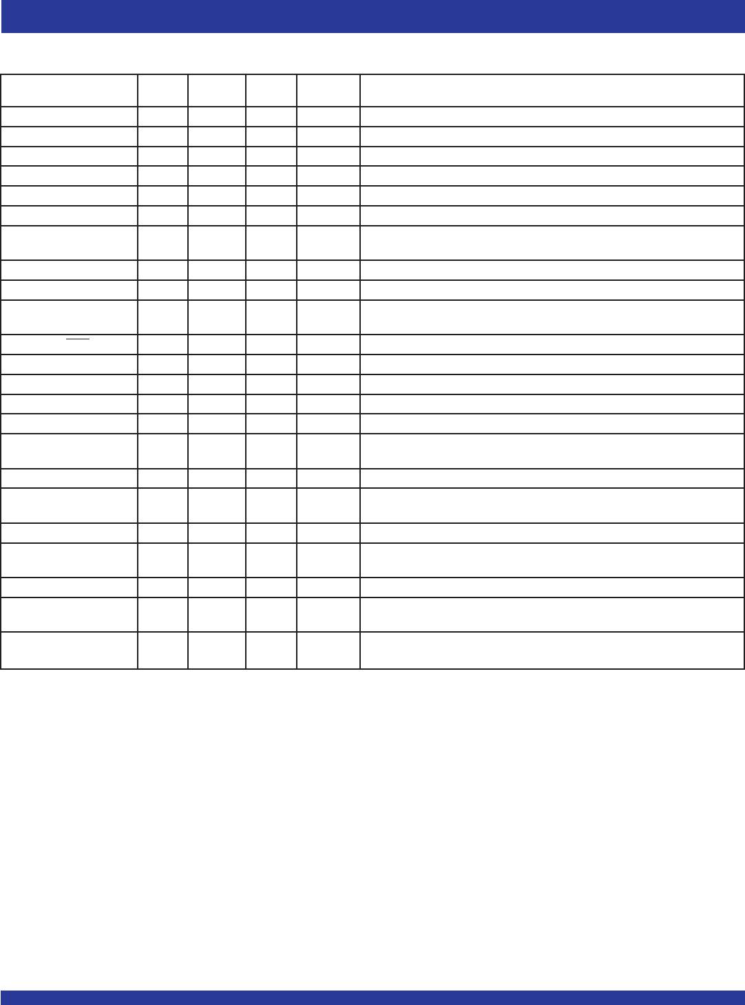
Spread Spectrum
Pre-Divider (D) Values Multiplier (M) Values Programmable Loop Bandwidth Generation Capability
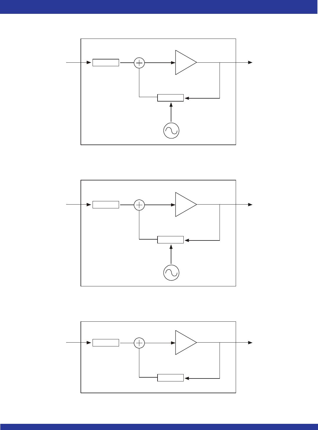
PLL0 1 - 255 2 - 8190 yes yes
PLL1 1 - 255 2 - 8190 yes yes
PLL2 1 - 255 1 - 4095 yes no
REFERENCE CLOCK INPUT PINS AND
SELECTION
The 5V9885T supports up to two clock inputs. One of the clock inputs
(XTALIN/ REFIN) can be driven by either an external crystal or a reference
clock. The second clock input (CLKIN) can only be driven from an external
reference clock. Either clock input can be set as a the primary clock. The primary
clock designation is to establish which is the main reference clock to the PLLs.
The non-primary clock is designated as the secondary clock in case the primary
clock goes absent and a backup is needed. The PRIMCLK bit (0x34)
determines which clock input will be the primary clock. When PRIMCLK bit is
"0", it will select XTALIN/REFIN as the primary, and when "1", it will select CLKIN
as the primary. The two external reference clocks can be manually selected
using the GIN5/CLK_SEL pin, except in Manual Frequency Control (MFC)
mode 2, or via programming by hard wiring the CLK_SEL pin and toggling the
PRIMCLK bit. For more details on the MFC modes, refer to the CONFIGURING
MULTI-PURPOSE I/Os section. When CLK_SEL is LOW, the primary clock
is selected and when HIGH, the secondary clock is selected. The SM bits (0x34)
must be set to "0x" for manual switchover which is detailed in SWITCHOVER
MODES section.
XTAL load cap = 3.5pF + XTALCAP[7:0] * 0.125pF (Eq. 1)
Crystal Input (XTALIN/REFIN)
The crystal oscillators should be fundamental mode quartz crystals: overtone
crystals are not suitable. Crystal frequency should be specified for parallel
resonance with 50Ω maximum equivalent series resonance.
When the XTALIN/REFIN pin is driven by a crystal, it is important to set the
internal oscillator inverter drive strength and internal tuning/load capacitor
values correctly to achieve the best clock performance. These values are
programmable through either I
2
C or JTAG interface to allow for maximum
compatibility with crystals from various manufacturers, processes, performances,
and qualities. The internal load capacitors are true parallel-plate capacitors for
ultra-linear performance. Parallel-plate capacitors were chosen to reduce the
frequency shift that occurs when non-linear load capacitance interacts with load,
bias, supply, and temperature changes. External non-linear crystal load
capacitors should not be used for applications that are sensitive to absolute
frequency requirements. The value of the internal load capacitors are determined
by XTALCAP[7:0] bits, (0x07). The load capacitance can be set with a resolution
of 0.125 pF for a total crystal load range of 3.5pF to 35.5pF. This value should
be set to two times the crystal load capacitance value stated by the vendor,
subtracting out board capacitance value. Check with the vendor's crystal load
capacitance specification for the exact setting to tune the internal load capacitor.
The following equation governs how the total internal load capacitance is set.
Ex.: For crystal capacitance = 12pF
For board capacitance = 3pF each leg
XTALCAP = 2x [12-3] = 18pF
GIN5/CLK_SEL Selected Clock Input
L Primary
H Secondary
Parameter Bits Step Min Max Units
XTALCAP 8 0.125 0 32 pF
When using an external reference clock instead of a crystal on the XTAL/
REFIN pin, the input load capacitors may be completely bypassed. This allows
for the input frequency to be up to 200MHz. When using an external reference
clock, the XTALOUT pin must be left floating, XTALCAP must be programmed
to the default value of "0", and crystal drive strength bit, XDRV (0x06), must
be set to the default value of "11".
CLKIN Pin
CLKIN pin is a regular clock input pin, and can be driven up to 400MHz.
PRE-SCALER, FEEDBACK-DIVIDER, AND
POST-DIVIDER
Each PLL incorporates an 8-bit pre-scaler and a 12-bit feedback divider
which allows the user to generate three unique non-integer-related frequencies.
For output banks OUT2-OUT6, each bank has a 10-bit post-divider. The
following equation governs how the frequency on output banks OUT2-6 is
calculated.
FOUT = FIN * D (Eq. 2)
Where FIN is the reference frequency, M is the total feedback-divider value,
D is the pre-scaler value, P is the total post-divider value, and FOUT is the resulting
output bank frequency. The value 2 in the denominator is due to the divide-
by-2 on each of the output banks OUT2-6. Note that OUT1 does not have any
type of post-divider. Also, programming any of the dividers may cause glitches
on the outputs.
Pre-Scaler
D[7:0] are the bits used to program the pre-scaler for each PLL, D0 for
PLL0, D1 for PLL1, and D2 for PLL2. The pre-scalers divide down the
reference clock with integer values ranging from 1 to 255. To maintain low jitter,
the divided down clock must be higher than 400KHz; it is best to use the smallest
D divider value possible. If D is set to '0x00', then this will power down the PLL
and all the outputs associated with that PLL.
M
P * 2
( )