WM8737L Production Data
w
PD, Rev 4.4, January 2012
16
MICROPHONE PREAMPLIFER BYPASS AND BIAS CONTROL
When the Left or Right microphone preamplifier is disabled the user has two options for driving the
corresponding Left or Right PGA.
Default operation is to close a preamplifier bypass switch that connects the PGA input directly to the
L/RINPUT1/2/3 multiplexer output.
If the application has only a single left or right line level signal source and hence does not require the
multiplexer or microphone preamplifier, then better PGA gain accuracy and THD+N performance are
obtained by disabling the multiplexer and bypass switch and driving the PGA directly via the L/RACIN
pin. The multiplexer and switch are disabled by setting to zero the appropriate L/RBYPEN bit in
register R9. The L/RINPUT1/2/3 pads remain biased to VREF. These bits should be set to 1 if the
multiplexer is required (always required when the microphone preamplifier is enabled).
The user can also adjust the microphone preamplifier bias settings to optimise THD+N versus supply
current consumption for their application. Default is full bias for best THD+N performance, but the
user can reduce the bias to 75%, 50% or 25% of default by programming MBCTRL[1:0] in register R9.
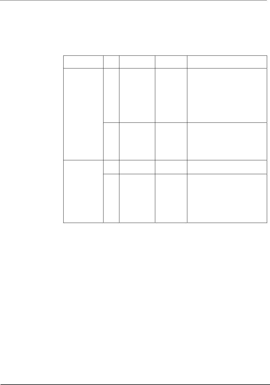
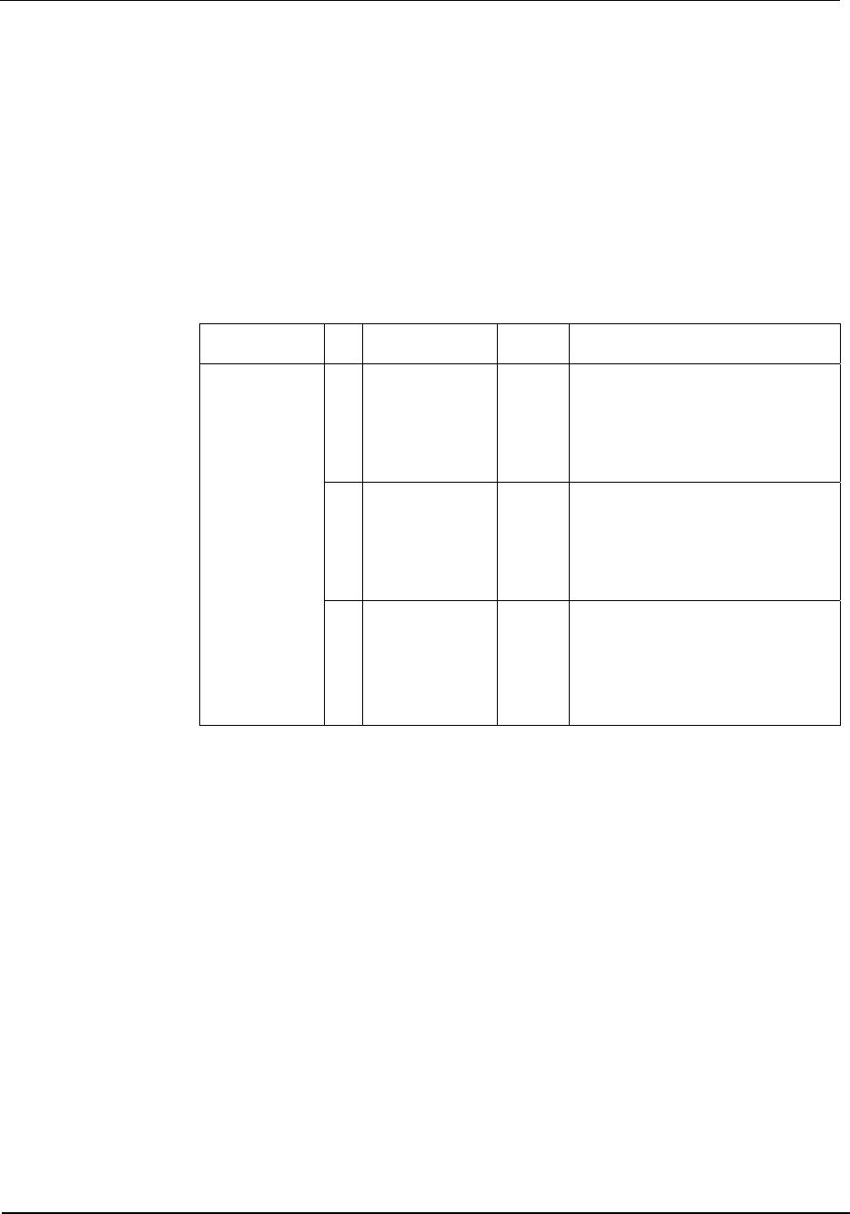
REGISTER
ADDRESS
BIT LABEL DEFAULT DESCRIPTION
R9 (09h)
Microphone
Preamplifiers
Control
3
RBYPEN 1 Right channel bypass enable
0: Bypass switch is always open.
RINPUT1/2/3 high-impedance biased to
AVDD/2. RPGA input is RACIN pin.
1: Close bypass switch when right mic
preamp is disabled.
2
LBYPEN 1 Left channel bypass enable
0: Bypass switch is always open.
LINPUT1/2/3 high-impedance biased to
AVDD/2. LPGA input is LACIN pin.
1: Close bypass switch when left mic
preamp is disabled.
1:0
MBCTRL[1:0] 11 Bias control for left and right
microphone preamplifiers
00: bias 25%
01: bias 50%
10: bias 75%
11: nominal (100%) bias
Table 4 Microphone Preamplifier Control
MONO-MIXING
The WM8737L can operate as a stereo or mono device, or the two channels can be mixed to mono in
either the analogue domain (before the ADC) or in the digital domain (after the ADC). In all mono and
mono-mix modes unused circuitry can be switched off to save power (see “Power Management”
section). 3D stereo enhancement (See “3D Stereo Enhancement” section) is automatically disabled in
all mono and mono-mix modes.
In analogue mono-mix mode, the signals are mixed in the Left ADC and the Right ADC automatically
switches to dc measurement mode on pin RINPUT1. If dc measurement mode is not required then
the Right ADC can be powered down by setting bit 2 (ADCR) in the power management register R6.
Note that the high pass filter must be disabled if d.c. measurements are required.
In stereo and mono modes the Left/Right ADC data appear at the corresponding Left/Right Channel
outputs. In digital mono-mix mode the mixed data appears on both the Left and Right Channel
outputs. In analogue mono-mix mode the MONOUT bit controls whether the Right channel output
presents the data from the Right ADC (dc measurement) or a copy of the Left Channel (mixed)
output.
Production Data WM8737L
w
PD, Rev 4.4, January 2012
17
REGISTER
ADDRESS
BIT LABEL DEFAULT DESCRIPTION
R5 (05h)
ADC Control
8:7
MONOMIX[1:0] 00 00: Stereo
01: Analogue Mono-mix
10: Digital Mono-mix
11: Reserved
R5 (05h)
ADC Control
1
MONOUT 0 Analogue mono-mix format control
0: Left ADC data appears on Left
Channel output and Right ADC data
appears on Right Channel Output.
1: Left ADC data appears on both Left
and Right channel outputs.
Table 5 Mono Mixing Control
Note: In stereo mode (R5) 00, Bit 1 must always be set to 0.
MICROPHONE BIAS
The MICBIAS output provides a low noise reference voltage suitable for biasing electret type
microphones and the associated external resistor biasing network. The output voltage is derived from
VREF and is programmable in three steps from 0.75 AVDD to 1.2 AVDD, as shown below. Supply
voltage MVDD must be at least 170mV higher than the desired MICBIAS voltage to ensure correct
MICBIAS operation.
REGISTER
ADDRESS
BIT LABEL DEFAULT DESCRIPTION
R6 (06h)
Power
Management
1:0
MICBIAS[1:0] 00 Microphone Bias Control
00: MICBIAS OFF (powered down,
high-impedance output)
01: V
MICBIAS
= 0.75 AVDD
10: V
MICBIAS
= 0.9 AVDD
11: V
MICBIAS
= 1.2 AVDD
Table 6 MICBIAS Control
The internal MICBIAS circuitry is shown below. MVDD is a separate power supply pin used only for
MICBIAS and the microphone preamplifiers. When MICBIAS < AVDD, then MVDD can be tied to
AVDD. However, when MICBIAS = 1.2 AVDD, then MVDD must be large enough to generate this
output voltage, i.e. it must be higher than AVDD.
Note: The maximum voltage for MVDD of 3.6V must be observed.
AGND
MICBIAS
VREF
internal
resistor
MVDD
Figure 6 Microphone Bias Schematic
Note that the maximum source current capability for MICBIAS is 3mA. The external biasing resistors
therefore must be large enough to limit the MICBIAS current to 3mA. Please refer to the “Applications
Information” section for recommended external components.
WM8737L Production Data
w
PD, Rev 4.4, January 2012
18
PGA CONTROL
The Left and Right PGAs match the input signal levels to the ADC input ranges. The PGA gain is
logarithmically adjustable from –97dB to +30dB in 0.5dB steps. Each PGA can be controlled either by
the user or by the ALC function (see “Automatic Level Control” section). When ALC is enabled for one
or both channels then writing to the corresponding PGA gain control register has no effect. The gain
is independently adjustable on both Right and Left Line Inputs. By setting the LVU or RVU bits whilst
programming the PGA gain, both channels can be simultaneously updated. The inputs can also be
muted under software control. The PGA control register maps are shown in Table 7.
REGISTER
ADDRESS
BIT LABEL DEFAULT DESCRIPTION
R0 (00h)
Left Channel
PGA
7:0
LINVOL[7:0] C3h
( 0dB )
Left Channel Input Volume Control
00000000: MUTE
00000001: -97dB
00000010: -96.5dB
11000011: 0dB
11111111: +30dB
8
LVU 0 Left PGA volume update
0: Store LINVOL in left intermediate
latch but do not update left gain.
1: Update both PGA gains
simultaneously (left gain = LINVOL,
right gain = right intermediate latch).
R1 (01h)
Right Channel
PGA
7:0
RINVOL[7:0] C3h
( 0dB )
Right Channel Input Volume Control.
Same as LINVOL.
8
RVU 0 Right PGA volume update
0: Store RINVOL in right
intermediate latch but do not update
right gain.
1: Update both PGA gains
simultaneously (right gain =
RINVOL, left gain = left intermediate
latch).
Table 7 PGA Software Control
ZERO-CROSS DETECTION
To avoid zipper or click noises, it is preferable to change the microphone preamplifier and PGA gains
only when the input signal is at zero. The WM8737L has built-in zero-cross detectors to achieve this.
This function is enabled by setting the LMZC, LPZC, RMZC and RPZC bits. The zero-cross detection
feature includes a programmable time-out, selected by writing to LZCTO[1:0] and RZCTO[1:0]. If no
zero crossing occurs within the time-out period then the WM8737L changes the PGA or microphone
preamplifier gains when the time-out elapses.

WM8737CLGEFL/R

Mfr. #:
Manufacturer:
Cirrus Logic
Description:
Audio A/D Converter ICs Stereo ADC Low Power
Lifecycle:
New from this manufacturer.
Delivery:
DHL FedEx Ups TNT EMS
Payment:
T/T Paypal Visa MoneyGram Western Union

Products related to this Datasheet