Production Data WM8737L
w
PD, Rev 4.4, January 2012
19
REGISTER
ADDRESS
BIT LABEL DEFAULT DESCRIPTION
R2 (02h)
Audio Path Left
3
LMZC None (first
gain
change
would
overwrite!)
Left Mic preamp Zero-Cross Enable
0: Change gain immediately
1: Change gain on zero crossing only
2
LPZC 1 Left PGA Zero-Cross Enable
0: Change gain immediately
1: Change gain on zero crossing only
1:0
LZCTO[1:0] 11 Left Zero-Cross Time-Out
00: 256/fs
01: 512/fs
10: 1024/fs
11: 2048/fs (42.67ms at 48kHz)
This timeout applies to both the PGA
and mic preamp zero-cross watchdog
timers.
R3 (03h)
Audio Path
Right
3
RMZC None Right Mic preamp Zero-Cross Enable
Same as LMZC but for right channel
2
RPZC 1 Right PGA Zero-Cross Enable
Same as LMZC but for right channel
1:0
RZCTO[1:0] 11 Right Zero-Cross Time-Out
Same as LMZC but for right channel
Table 8 Zero-Cross Detection Control
ANALOGUE TO DIGITAL CONVERTER (ADC)
The WM8737L uses a multi-bit, oversampled sigma-delta ADC for each channel. The use of multi-bit
feedback and high oversampling rates reduces the effects of jitter and high frequency noise. The ADC
full-scale input level is proportional to AVDD. With a 3.3V supply voltage the full scale level is 1.0 Volt
rms (+/-1.414 Volts peak). Any voltage greater than full-scale will overload the ADC and cause
distortion.
ADC THD+N VERSUS POWER CONTROL
The ADCs can be operated in ‘normal mode’, which offers best THD+N performance at the cost of
highest power dissipation, or in ‘low power mode’ which offers significant power savings at the cost of
slightly reduced THD+N performance. The ADCs operating mode is controlled by the LP bit in register
R5. USB mode is not compatible with low power mode, so the LP bit must be set to 0 if USB mode is
selected.
See the ‘Power Consumption’ section for power requirements in both modes.
REGISTER
ADDRESS
BIT LABEL DEFAULT DESCRIPTION
R5 (05h)
ADC Control
2
LP 0 ADC power mode control
0: Both ADCs in normal mode (best
THD+N)
1: Both ADCs in low power mode
Table 9 ADC Power Control
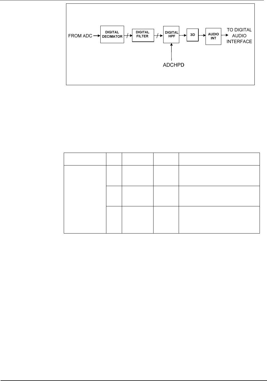
ADC DIGITAL FILTER
The ADC filters perform true 24 bit signal processing to convert the raw multi-bit oversampled data
from the ADC to the correct sampling frequency to be output on the digital audio interface. The digital
filter path is illustrated below.
WM8737L Production Data
w
PD, Rev 4.4, January 2012
20
Figure 7 ADC Digital Filter
The ADC digital filters contain a digital high pass filter, selectable via software control. The high-pass
filter response is detailed in the “Digital Filter Characteristics” section. When the high-pass filter is
enabled the dc offset is continuously calculated and subtracted from the input signal. By setting
HPOR, the last calculated d.c. offset value is maintained but still subtracted from the input.
The output data format can be programmed by the user to accommodate stereo or monophonic
recording on both inputs. The polarity of the output signal can also be changed under software
control. The software control is shown below.
REGISTER
ADDRESS
BIT LABEL DEFAULT DESCRIPTION
R5 (05h)
ADC Control
0 ADCHPD 0 ADC High Pass Filter Enable (Digital)
1: Disable High Pass Filter
0: Enable High Pass Filter
4 HPOR 0 Store dc offset
0: Present offset maintained
1: Continuously update offset
6:5 POLARITY 00 00: Polarity not inverted
01: L polarity invert
10: R polarity invert
11: L and R polarity invert
Table 10 ADC Control
ADC MAXIMUM OUTPUT CODES
The ADC output codes are limited by the digital gain of the stage following the 3D enhancement
filters. This limits the max full scale positive output to 7F7FFFh and full scale negative to 808000h. To
get the maximum positive output code (7FFFFFh) and negative code (800000h) from the ADC, the 3D
enhancement filters should be bypassed. This can be done by first setting register R13 (0Dh) to
1_110x_xxxx (1C0h), where x_xxxx represents the required values for the ALC in the application, and
then setting register R28 (1Ch) to 0_0000_0100 (004h).
Note that the above sequence uses test bits that are not documented and the use of these test bits,
other than as described above, is not recommended and is not supported.
3D STEREO ENHANCEMENT
The WM8737L has a 3D stereo enhancement function for use in applications where the natural
separation between stereo channels is low. The function is activated by the 3DEN bit, and artificially
increases the separation between the left and right channels. The 3DDEPTH setting controls the
degree of stereo expansion. Additionally, one of four filter characteristics can be selected for the 3D
processing, using the 3DFILT control bits.
When 3D enhancement is enabled (and/or the tone control for playback) it may be necessary to
attenuate the signal by 6dB to avoid limiting. This is a user selectable function, enabled by setting
DIV2.
Production Data WM8737L
w
PD, Rev 4.4, January 2012
21
Note: The 3D enhancement function is not supported at sample frequencies of 88.2kHz, 88.235kHz,
and 96kHz. When using these sample frequencies the 3D enhancement function should be bypassed
by first setting register R13 (0Dh) to 1_110x_xxxx (1C0h), where x_xxxx represents the required
values for the ALC in the application, and then setting register R28 (1Ch) to 0_0000_0100 (004h).
Note that the above sequence uses test bits that are not documented and the use of these test bits,
other than as described above, is not recommended and is not supported.
REGISTER
ADDRESS
BIT LABEL DEFAULT DESCRIPTION
R4 (04h)
3D Control
0 3DEN 0 3D function enable
0: disable
1: enable
4:1 3DDEPTH[3:0] 0000 Stereo depth
0000: 0% (minimum 3D effect)
0001: 6.67%
....
1110: 93.3%
1111: 100% (maximum 3D effect)
5 3DUC 0 Upper Cut-off frequency
0 = High (2.2kHz at 48kHz sampling)
1 = Low (1.5kHz at 48kHz sampling)
6 3DLC 0 Lower Cut-off frequency
0 = Low (200Hz at 48kHz sampling)
1 = High (500Hz at 48kHz sampling)
7 DIV2 0 ADC 6dB attenuate enable
0: disabled (0dB)
1: -6dB enabled
Table 11 Stereo Enhancement Control
AUTOMATIC LEVEL CONTROL (ALC)
The WM8737L has an automatic level control that aims to keep a constant recording volume
irrespective of the input signal level. This is achieved by continuously adjusting the PGA gain so that
the signal level at the ADC input remains constant. A digital peak detector monitors the ADC output
and changes the PGA gain if necessary.
hold
time
decay
time
attack
time
input
signal
signal
after
ALC
PGA
gain
ALC
target
level
Figure 8 ALC Operation

WM8737CLGEFL/R

Mfr. #:
Manufacturer:
Cirrus Logic
Description:
Audio A/D Converter ICs Stereo ADC Low Power
Lifecycle:
New from this manufacturer.
Delivery:
DHL FedEx Ups TNT EMS
Payment:
T/T Paypal Visa MoneyGram Western Union

Products related to this Datasheet