Production Data WM8737L
w
PD, Rev 4.4, January 2012
25
MASTER AND SLAVE MODE OPERATION
The WM8737L can be configured as either a master or slave mode device. As a master device the
WM8737L generates BCLK and ADCLRC and thus controls sequencing of the data transfer on
ADCDAT. In slave mode, the WM8737L responds with data to clocks it receives over the digital audio
interface. The mode can be selected by writing to the MS bit (see Table 14). Master and slave modes
are illustrated below.
BCLK
ADCDAT
ADCLRC
WM8737
ADC
DSP /
ENCODER
BCLK
ADCDAT
ADCLRC
WM8737
ADC
DSP /
ENCODER
Figure 9a Master Mode Figure 9b Slave Mode
AUDIO DATA FORMATS
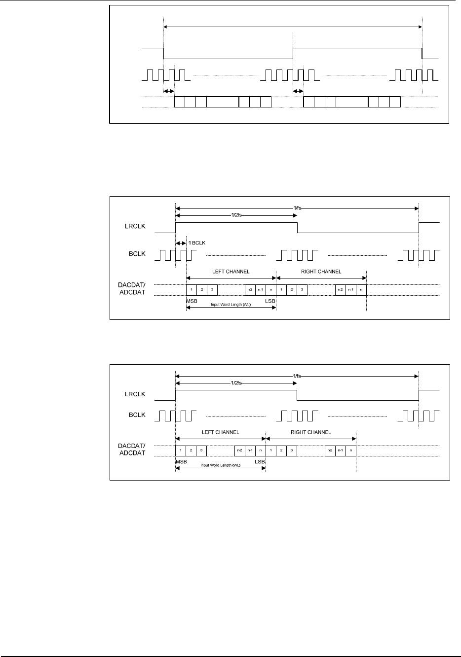
In Left Justified mode, the MSB is available on the first rising edge of BCLK following an ADCLRC
transition. The other bits up to the LSB are then transmitted in order. Depending on word length,
BCLK frequency and sample rate, there may be unused BCLK cycles before each ADCLRC
transition.
LEFT CHANNEL RIGHT CHANNEL
ADCLRC
BCLK
ADCDAT
1/fs
n321
n-2 n-1
LSBMSB
n321
n-2 n-1
LSBMSB
Figure 10 Left Justified Audio Interface (assuming n-bit word length)
In Right Justified mode, the LSB is available on the last rising edge of BCLK before an ADCLRC
transition. All other bits are transmitted before (MSB first). Depending on word length, BCLK
frequency and sample rate, there may be unused BCLK cycles after each ADCLRC transition.
LEFT CHANNEL RIGHT CHANNEL
ADCLRC
BCLK
ADCDAT
1/fs
n321
n-2 n-1
LSBMSB
n321
n-2 n-1
LSBMSB
Figure 11 Right Justified Audio Interface (assuming n-bit word length)
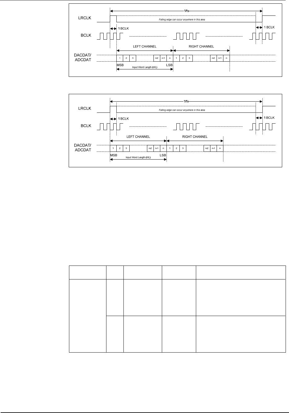
In I
2
S mode, the MSB is available on the second rising edge of BCLK following an ADCLRC
transition. The other bits up to the LSB are then transmitted in order. Depending on word length,
BCLK frequency and sample rate, there may be unused BCLK cycles between the LSB of one sample
and the MSB of the next.
WM8737L Production Data
w
PD, Rev 4.4, January 2012
26
LEFT CHANNEL RIGHT CHANNEL
ADCLRC
BCLK
ADCDAT
1/fs
n321
n-2 n-1
LSB
MSB
n321
n-2 n-1
LSB
MSB
1 BCLK
1 BCLK
Figure 12 I
2
S Justified Audio Interface (assuming n-bit word length)
In DSP mode, the left channel MSB is available on either the 1
st
or 2
nd
rising edge of BCLK
(selectable by LRP) following a rising edge of ADCLRC. Right channel data immediately follows left
channel data. Depending on word length, BCLK frequency and sample rate, there may be unused
BCLK cycles between the LSB of the right channel data and the next sample.
Figure 13 DSP Mode A Mater Mode
Figure 14 DSP Mode B, Master Mode Audio Interface
Production Data WM8737L
w
PD, Rev 4.4, January 2012
27
Figure 15 DSP Mode A Slave Mode
Figure 16 DSP Mode B Slave Mode
AUDIO INTERFACE CONTROL
The register bits controlling audio format, word length and master/slave mode are summarised below.
Note that dynamically changing the software format may cause erroneous operation of the interfaces
and is therefore not recommended.
All ADC data is signed 2’s complement. The length of the digital audio data is programmable at
16/20/24 or 32 bits, as shown below. The ADC digital filters process data using 24 bits. If the
WM8737L is programmed to output 16 or 20 bit data then it strips the LSBs from the 24 bit data. If the
device is programmed to output 32 bits then it packs the LSBs with zeros.
REGISTER
ADDRESS
BIT LABEL DEFAULT DESCRIPTION
R7 (07h)
Digital Audio
Interface
Format
1:0 FORMAT 10 Audio Data Format Select
11: DSP Mode
10: I
2
S Format
01: Left justified
00: Right justified
3:2 WL 10 Audio Data Word Length
11: 32 bits (see Note)
10: 24 bits
01: 20 bits
00: 16 bits

WM8737CLGEFL/R

Mfr. #:
Manufacturer:
Cirrus Logic
Description:
Audio A/D Converter ICs Stereo ADC Low Power
Lifecycle:
New from this manufacturer.
Delivery:
DHL FedEx Ups TNT EMS
Payment:
T/T Paypal Visa MoneyGram Western Union

Products related to this Datasheet