WM8737L Production Data
w
PD, Rev 4.4, January 2012
36
APPLICATIONS INFORMATION
LINE INPUT CONFIGURATION
In order to avoid clipping, the user must ensure that the input signal does not exceed AVDD. This
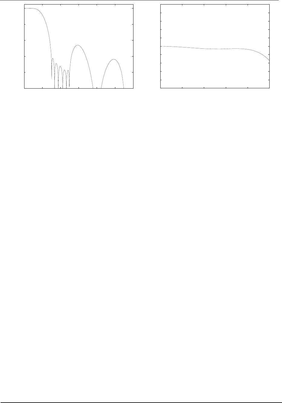
may require a potential divider circuit in some applications. It is also recommended to remove RF
interference picked up on any cables using a simple first-order RC filter, as high-frequency
components in the input signal may otherwise cause aliasing distortion in the audio band. This filter
must not have high output impedance at audio frequencies (e.g. use a LC filter) if PGA gain errors are
to be minimised when bypassing the microphone preamplifier.
When using ac signals with no dc bias they should be coupled to the WM8737L signal inputs through
a DC blocking capacitor, e.g. 470nF or 1F when using the microphone preamplifier, and at least
10F if directly driving the PGA (bigger capacitance may be required at higher gains due to the low
PGA input impedance at high gain).
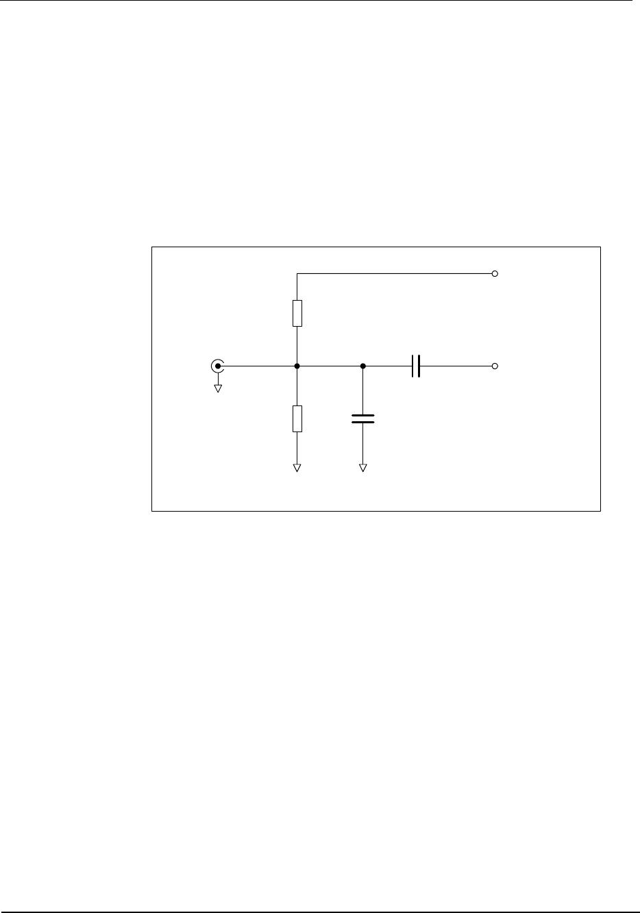
MICROPHONE INPUT CONFIGURATION
R2
47KOhm
C1
220pF
C2
1uF
AGND
AGND AGND
LINPUT1/2/3
RINPUT1/2/3
FROM
MICROPHONE
R1
680 Ohm
MICBIAS
Figure 27 Recommended Circuit for Microphone Input
For interfacing to a microphone, the ALC function should be enabled and the microphone boost
switched on. Microphones held close to a speaker’s mouth would normally use a lower boost setting
such as 13dB, while tabletop or room microphones would need a higher boost, for example 28dB.
The recommended application circuit is shown above. R1 and R2 form part of the biasing network
(refer to Microphone Bias section). R1 connected to MICBIAS is necessary only for electret type
microphones that require a voltage bias. R2 should always be present to prevent the microphone
input from charging to a high voltage which may damage the microphone on connection. R1 and R2
should be large so as not to attenuate the signal from the microphone, which can have source
impedance greater than 2k. C1 together with the source impedance of the microphone and the
WM8737L input impedance forms an RF filter. C2 is a dc blocking capacitor to allow the microphone
to be biased at a different dc voltage to the MICIN signal.