LTC6803-2/LTC6803-4
20
680324fa
Toggle Polling: Toggle polling allows a robust determina-
tion both of device states and of the integrity of the con-
nections between the devices in a stack. Toggle polling is
enabled when the LVLPL bit is low. After entering a polling
command, the data out line will be driven by the slave
devices based on their status. When polling for the ADC
converter status, data out will be low when any device is
busy performing an ADC conversion and will toggle at
1kHz when no device is busy. Similarly, when polling for
interrupt status, the output will be low when any device
has an interrupt condition and will toggle at 1kHz when
none has an interrupt condition.
Toggle Polling—Address Polling: The addressed device
drives the SDO line based on its state alone—low for busy/
in interrupt, toggling at 1kHz for not busy/not in interrupt.
Toggle Polling—Parallel Broadcast Polling: No part ad-
dress is sent, so all devices respond simultaneously. If a
device is busy/in interrupt, it will pull SDO low. If a device
is not busy/not in interrupt, then it will release the SDO line
(TOS = 0) or attempt to toggle the SDO line at 1kHz (TOS
= 1).The master controller pulls CSBI high to exit polling.
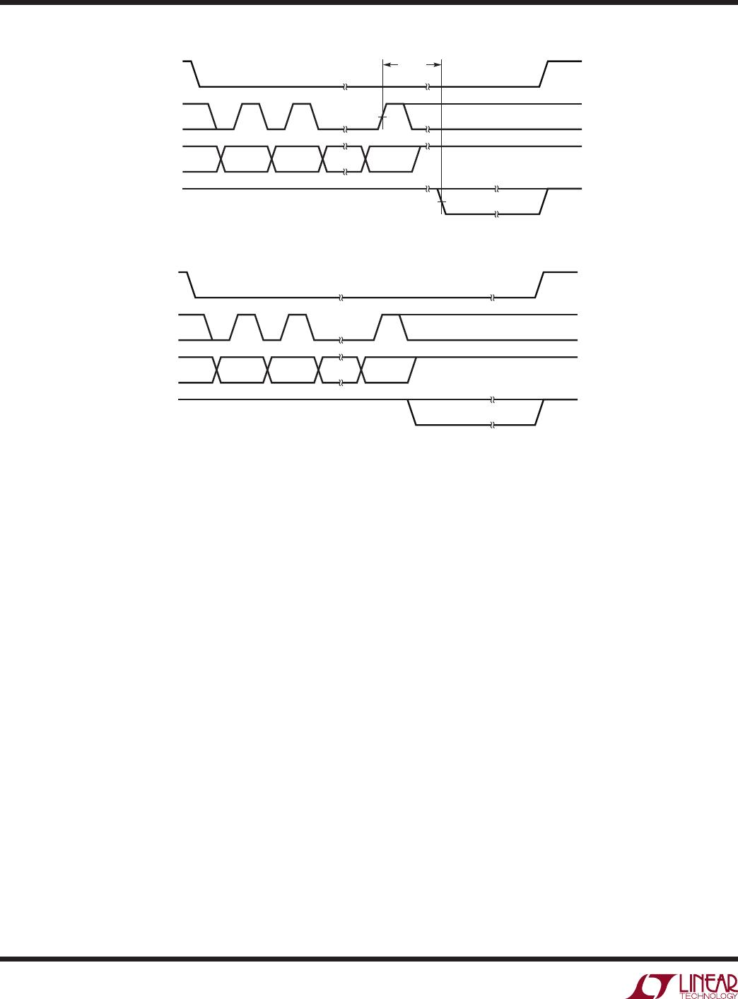
CSBI
SCKI
SDI
SDO
MSB (CMD)
BIT6 (CMD) LSB (PEC)
TOGGLE OR LEVEL POLL
t
CYCLE
680324 F05
CSBI
SCKI
SDI
SDO
MSB (CMD)
BIT6 (CMD) LSB (PEC)
TOGGLE OR LEVEL POLL
680324 F06
Figure 5. Transmission Format (ADC Conversion and Poll)
Figure 6. Transmission Format (PLADC Conversion or PLINT)
Level Polling: Level polling is enabled when the LVLPL
bit is high. After entering a polling command, the data
out line will be driven by the slave devices based on their
status. When polling for the ADC converter status, data
out will be low when any device is busy performing an
ADC conversion and will be high when no device is busy.
Similarly, when polling for interrupt status, the output will
be low when any device has an interrupt condition and will
be high when none has an interrupt condition.
Level Polling—Address Polling: The addressed device
drives the SDO line based on its state alone—pulled low
for busy/in interrupt, released for not busy/not in interrupt.
Level polling—Parallel Broadcast Polling: No part address
is sent, so all devices respond simultaneously. If a device
is busy/in interrupt, it will pull SDO low. If a device is not
busy/not in interrupt, then it will release the SDO line. If
any device is busy or in interrupt the SDO signal will be
low. If all devices are not busy/not in interrupt, the SDO
signal will be high. The master controller pulls CSBI high
to exit polling.
OPERATION