MT9V024/D
www.onsemi.com
21
Analog Gain
Analog gain is controlled by:
• R0x35 Global Gain context A
• R0x36 Global Gain context B
The formula for gain setting is:
Gain + Bits[6 : 0] x 0.0625
(eq. 16)
The analog gain range supported in the MT9V024 is
1X
–4X with a step size of 6.25 percent. To control gain
manually with this register, the sensor must NOT be in AGC
mode. When adjusting the luminosity of an image, it is
recommended to alter exposure first and yield to gain
increases only when the exposure value has reached
a maximum limit.
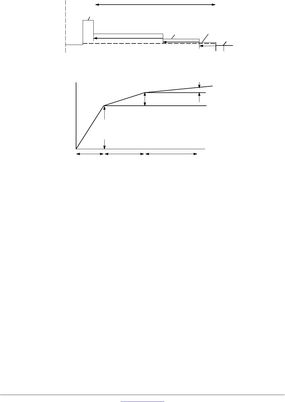
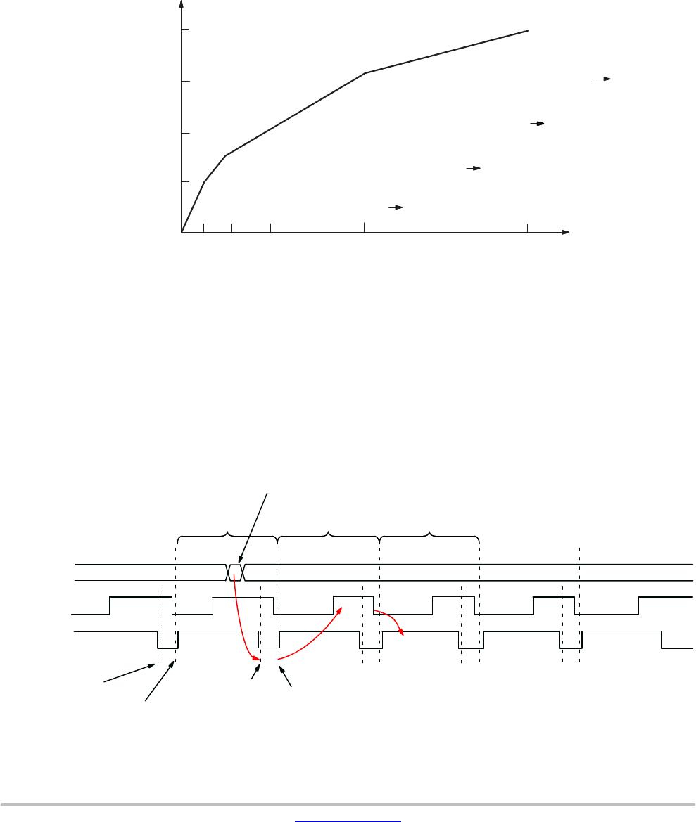
Analog gain = bits (6:0) x 0.0625 for values 16–31
Analog gain = bits (6:0)/2 x 0.125 for values 32–64
For values 16–31: each LSB increases analog gain
0.0625v/v. A value of 16 = 1X gain.
Range: 1X to 1.9375X.
For values 32–64: each 2 LSB increases analog gain
0.125v/v (that is, double the gain increase for 2 LSB).
Range: 2X to 4X. Odd values do not result in gain increases;
the gain increases by 0.125 for values 32, 34, 36, and so on.
Digital Gain
Digital gain is controlled by:
• R0x99−R0xA4 Tile Coordinates
• R0x80−R0x98 Tiled Digital Gain and Weight
In the MT9V024, the gain logic divides the image into 25
tiles, as shown in Figure 27. The size and gain of each tile can
be adjusted using the above digital gain control registers.
Separate tile gains can be assigned for context A and context
B.
Registers 0x99–0x9E and 0x9F–0xA4 represent the
coordinates X0/5–X5/5 and Y0/5–Y5/5 in Figure 27 on page
31, respectively.
Digital gains of registers 0x80–0x98 apply to their
corresponding tiles. The MT9V024 supports a digital gain
of 0.25–3.75X.
When binning is enabled, the tile offsets maintain their
absolute values; that is, tile coordinates do not scale with row
or column bin setting. Digital gain is applied as soon as
register is written.
NOTE: There is one exception, for the condition when
Column Bin 4 is enabled (R0x0D[3:2] or
R0x0E[3:2] = 2). For this case, the value for
Digital Tile Coordinate X–direction must be
doubled.
The formula for digital gain setting is:
Digital Gain + Bits[3 : 0] x 0.25
(eq. 17)
X
0/5
X
1/5
X
2/5
X
3/5
X
4/5
X
5/5
Y
0/5
Y
2/5
Y
1/5
Y
3/5
Y
4/5
Y
5/5
Figure 27. Tiled Sample
x0_y0 x1_y0
x4_y0
x0_y1 x1_y1
x4_y1
x0_y2 x1_y2
x4_y2
x0_y3 x1_y3
x4_y3
x0_y4 x1_y4
x4_y4
Black Level Calibration
Black level calibration is controlled by:
• Frame Dark Average: R0x42
• Dark Average Thresholds: R0x46
• Black Level Calibration Control: R0x47
• Black Level Calibration Value: R0x48
• Black Level Calibration Value Step Size: R0x4C
The MT9V024 has automatic black level calibration
on−chip, and if enabled, its result may be used in the offset
correction shown in Figure 28.