MT9V024/D
www.onsemi.com
7
COLOR (RGB BAYER) DEVICE LIMITATIONS
The color version of the MT9V024 does not support or
offers reduced performance for the following
functionalities.
Pixel Binning
Pixel binning is done on immediate neighbor pixels only,
no facility is provided to skip pixels according to a Bayer
pattern. Therefore, the result of binning combines pixels of
different colors. See “Pixel Binning” for additional
information.
Interlaced Readout
Interlaced readout yields one field consisting only of red
and green pixels and another consisting only of blue and
green pixels. This is due to the Bayer pattern of the CFA.
Automatic Black Level Calibration
When the color bit is set (R0x0F[1]=1), the sensor uses
black level correction values from one green plane, which
are applied to all colors. To use the calibration value based
on all dark pixels’ offset values, the color bit should be
cleared.
Defective Pixel Correction
For defective pixel correction to calculate replacement
pixel values correctly, for color sensors the color bit must be
set (R0x0F[1] = 1). However, the color bit also applies
unequal offset to the color planes, and the results might not
be acceptable for some applications.
Other Limiting Factors
Black level correction and rowwise noise correction are
applied uniformly to each color. The rowwise noise
correction algorithm does not work well in color sensors.
Automatic exposure and gain control calculations are made
based on all three colors, not just the green channel. High
dynamic range does operate in color; however,
ON Semiconductor strongly recommends limiting use to
linear operation where good color fidelity is required.
OUTPUT DATA FORMAT
The MT9V024 image data can be read out in a progressive
scan or interlaced scan mode. Valid image data is surrounded
by horizontal and vertical blanking, as shown in Figure 7.
The amount of horizontal and vertical blanking is
programmable through R0x05 and R0x06, respectively
(R0xCD and R0xCE for context B). LV is HIGH during the
shaded region of the figure. See “Output Data Timing” for
the description of FV timing.
VALID iMAGE HORIZONTAL
BLANKING
VERTICAL/HORIZONTAL
BLANKING
VERTICAL BLANKING
00 00 00 ………… 00 00 00
00 00 00 ………… 00 00 00
00 00 00 ………… 00 00 00
00 00 00 ………… 00 00 00
00 00 00 ………… 00 00 00
00 00 00 ………… 00 00 00
00 00 00 ………… 00 00 00
00 00 00 ………… 00 00 00
00 00 00 ………… 00 00 00
00 00 00 ………… 00 00 00
00 00 00 ………… 00 00 00
00 00 00 ………… 00 00 00
P
0,0
P
0,1
P
0,2
…………P
0,n1
P
0,n
P
1,0
P
1,1
P
1,2
…………P
1,n1
P
1,n
P
m1,0
P
m1,1
…………P
m1,n1
P
m1,n
P
m,0
P
m,1
…………P
m,n1
P
m,n
Figure 7. Spatial Illustration of Image Readout
Output Data Timing
The data output of the MT9V024 is synchronized with the
PIXCLK output. When LINE_VALID (LV) is HIGH, one
10bit pixel datum is output every PIXCLK period.
MT9V024/D
www.onsemi.com
8
LINE_VALID
PIXCLK
Blanking Valide Image Data Blanking
P
0
(9:0)
P
1
(9:0)
P
2
(9:0)
P
3
(9:0)
P
4
(9:0)
P
n1
(9:0)
P
n
(9:0)
Figure 8. Timing Example of Pixel Data
D
OUT
(9:0)
The PIXCLK is a nominally inverted version of the master
clock (SYSCLK). This allows PIXCLK to be used as a clock
to latch the data. However, when column bin 2 is enabled, the
PIXCLK is HIGH for one complete master clock master
period and then LOW for one complete master clock period;
when column bin 4 is enabled, the PIXCLK is HIGH for two
complete master clock periods and then LOW for two
complete master clock periods. It is continuously enabled,
even during the blanking period. Setting R0x72 bit[4] = 1
causes the MT9V024 to invert the polarity of the PIXCLK.
The parameters P1, A, Q, and P2 in Figure 9 are defined
in Table 2.
Figure 9. Row Timing and FRAME_VALID/LINE_VALID Signals
P1 A QA QAP2
FRAME_VALID
LINE_VALID
...
...
...
Number of master clocks
Table 4. FRAME TIME
Parameter Name Equation Default Timing at 26.66 MHz
A Active data time Context A: R0x04
Context B: R0xCC
752 pixel clocks
= 752 master = 28.20 s
P1 Frame start blanking Context A: R0x05 23
Context B: R0xCD 23
71 pixel clocks
= 71master = 2.66 s
P2 Frame end blanking 23 (fixed) 23 pixel clocks
= 23 master = 0.86 s
Q Horizontal blanking Context A: R0x05
Context B: R0xCD
94 pixel clocks
= 94 master = 3.52 s
A+Q Row time Context A: R0x04 + R0x05
Context B: R0xCC + R0xCD
846 pixel clocks
= 846 master = 31.72 s
V Vertical blanking Context A: (R0x03) x (A + Q) + 4
Context B: (R0xCB) x (A + Q) + 4
38,074 pixel clocks
= 38,074 master = 1.43 ms
Nrows x (A + Q) Frame valid time Context A: (R0x03) x (A + Q)
Context B: (R0xCB) x (A + Q)
406,080 pixel clocks
= 406,080 master = 15.23 ms
F Total frame time V + (Nrows x (A + Q)) 444,154 pixel clocks
= 444,154 master = 16.66 ms
Sensor timing is shown above in terms of pixel clock and
master clock cycles (refer to Figure 8). The recommended
master clock frequency is 26.66 MHz. The vertical blanking
and the total frame time equations assume that the
integration time (coarse shutter width plus fine shutter
width) is less than the number of active rows plus the
blanking rows minus the overhead rows:
Window Height ) Vertical Blanking * 2
(eq. 1)
If this is not the case, the number of integration rows must
be used instead to determine the frame time, as shown in
Table 3. In this example, it is assumed that the coarse shutter
width control is programmed with 523 rows and the fine
shutter width total is zero.
MT9V024/D
www.onsemi.com
9
For Simultaneous mode, if the exposure time registers
(coarse shutter width total plus Fine Shutter Width Total)
exceed the total readout time, then the vertical blanking time
is internally extended automatically to adjust for the
additional integration time required. This extended value is
not written back to the vertical blanking registers. The
vertical blank register can be used to adjust frametoframe
readout time. This register does not affect the exposure time
but it may extend the readout time.
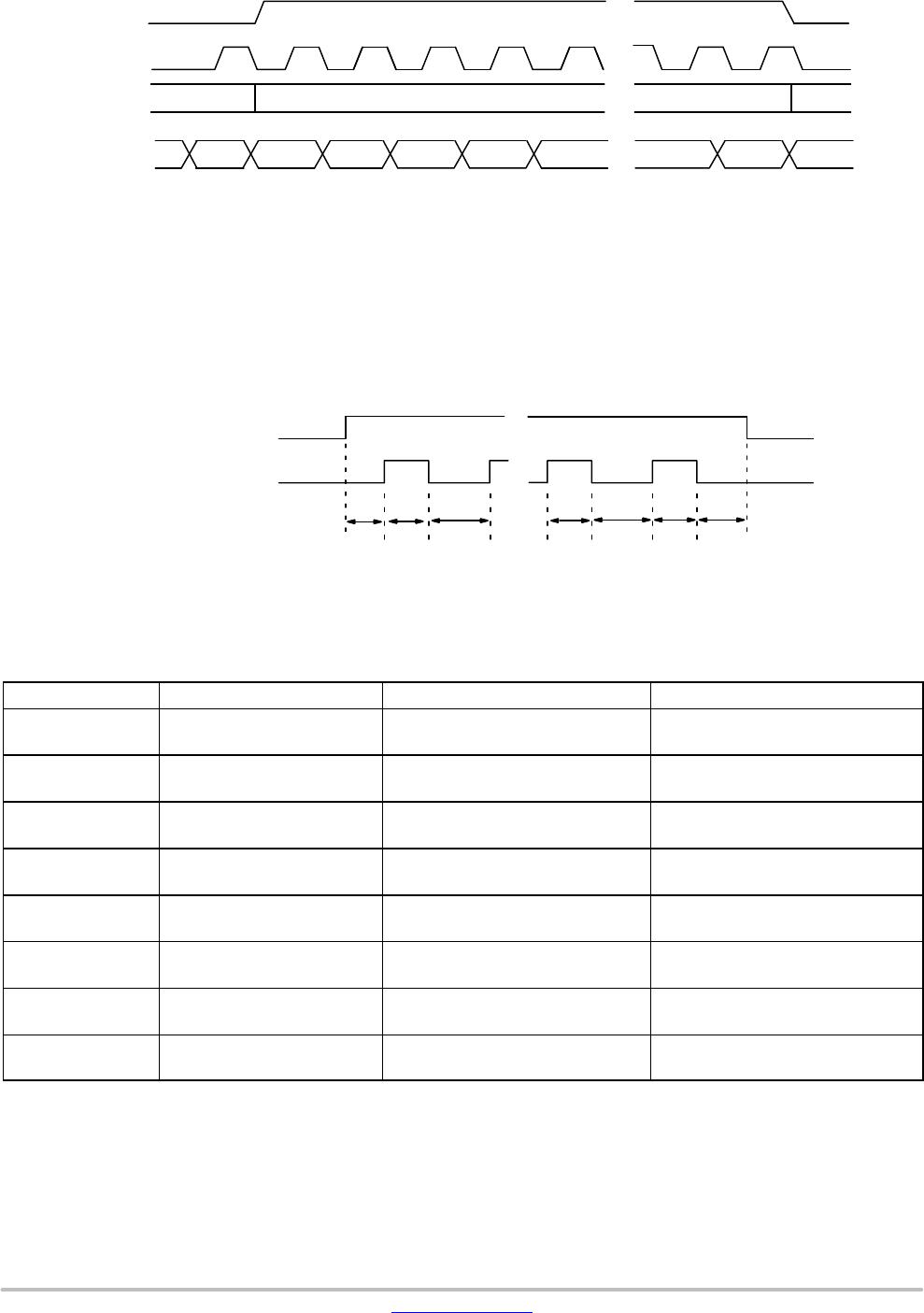
Table 5. FRAME TIME LONG INTEGRATION TIME
Parameter Name
Equation
(Number of Master Clock Cycles)
Default Timing at 26.66 MHz
V’ Vertical blanking (long integration
time)
Context A: (R0x0B + 2 R0x03) ×
(A + Q) + R0xD5 + 4
Context B: (R0xD2 + 2 R0xCB) ×
(A + Q) + R0xD8 + 4
38,074 pixel clocks
= 38,074 master = 1.43ms
F” Total frame time (long integration
exposure time)
(R0x0B + 2) × (A + Q) + 4 444,154 pixel clocks
= 444,154 master = 16.66ms
4. The MT9V024 uses column parallel analogdigital converters; thus short row timing is not possible. The minimum total row time is 704
columns (horizontal width + horizontal blanking). The minimum horizontal blanking is 61 for normal mode, 71 for column bin 2 mode, and 91
for column bin 4 mode. When the window width is set below 643, horizontal blanking must be increased. In binning mode, the minimum row
time is R0x04+R0x05 = 704.
SERIAL BUS DESCRIPTION
Registers are written to and read from the MT9V024
through the twowire serial interface bus. The MT9V024
is a serial interface slave with four possible IDs (0x90, 0x98,
0xB0 and 0xB8) determined by the S_CTRL_ADR0 and
S_CTRL_ADR1 input pins. Data is transferred into the
MT9V024 and out through the serial data (S
DATA) line. The
S
DATA line is pulled up to VDD offchip by a 1.5 k resistor.
Either the slave or master device can pull the S
DATA line
downthe serial interface protocol determines which device
is allowed to pull the S
DATA line down at any given time. The
registers are 16bit wide, and can be accessed through 16or
8bit twowire serial interface sequences.
Protocol
1. a start bit
2. the slave device 8bit address
3. a(n) (no) acknowledge bit
4. an 8bit message
5. a stop bit
Start Bit
The start bit is defined as a HIGHtoLOW transition of
the data line while the clock line is HIGH.
Slave Address
The 8bit address of a twowire serial interface device
consists of 7 bits of address and
1 bit of direction. A “0” in the LSB of the address indicates
write mode, and a “1” indicates read mode. As indicated
above, the MT9V024 allows four possible slave addresses
determined by the two input pins, S_CTRL_ADR0 and
S_CTRL_ADR1.
Acknowledge Bit
The master generates the acknowledge clock pulse. The
transmitter (which is the master when writing, or the slave
when reading) releases the data line, and the receiver
indicates an acknowledge bit by pulling the data line LOW
during the acknowledge clock pulse.
NoAcknowledge Bit
The noacknowledge bit is generated when the data line
is not pulled down by the receiver during the acknowledge
clock pulse. A noacknowledge bit is used to terminate
a read sequence.
Stop Bit
The stop bit is defined as a LOWtoHIGH transition of
the data line while the clock line is HIGH.
Sequence
A typical READ or WRITE sequence begins by the
master sending a start bit. After the start bit, the master sends
the slave devices 8bit address. The last bit of the address
determines if the request is a read or a write, where a “0”
indicates a WRITE and a “1” indicates a READ. The slave
device acknowledges its address by sending an
acknowledge bit back to the master.
If the request was a WRITE, the master then transfers the
8bit register address to which a WRITE should take place.
The slave sends an acknowledge bit to indicate that the
register address has been received. The master then transfers
the data 8 bits at a time, with the slave sending an
acknowledge bit after each 8 bits. The MT9V024 uses
16bit data for its internal registers, thus requiring two 8bit
transfers to write to one register. After 16 bits are transferred,
the register address is automatically incremented, so that the
next 16 bits are written to the next register address. The
master stops writing by sending a start or stop bit.
A typical READ sequence is executed as follows. First the
master sends the write mode slave address and 8bit register
address, just as in the write request. The master then sends
a start bit and the read mode slave address. The master then

MT9V024IA7XTM-DP2

Mfr. #:
Manufacturer:
ON Semiconductor
Description:
Image Sensors VGA 1/3 GS CIS Image Sensor
Lifecycle:
New from this manufacturer.
Delivery:
DHL FedEx Ups TNT EMS
Payment:
T/T Paypal Visa MoneyGram Western Union