XR16C864
16
2.97V TO 5.5V QUAD UART WITH 128-BYTE FIFO
REV. 2.2.0
N
OTE
: Table-B selected as Trigger Table for
Figure 9
(
Table 11
).
2.14 Auto RTS Hardware Flow Control
Automatic RTS hardware flow control is used to prevent data overrun to the local receiver FIFO. The RTS#
output is used to request remote unit to suspend/resume data transmission. The auto RTS flow control
features is enabled to fit specific application requirement (see Figure 10):
Enable auto RTS flow control using EFR bit-6.
The auto RTS function must be started by asserting RTS# output pin (MCR bit-1 to logic 1 after it is enabled).
If using the Auto RTS interrupt:
Enable RTS interrupt through IER bit-6 (after setting EFR bit-4). The UART issues an interrupt when the
RTS# pin makes a transition from low to high: ISR bit-5 will be set to logic 1.
F
IGURE
8. R
ECEIVER
O
PERATION
IN
NON
-FIFO M
ODE
F
IGURE
9. R
ECEIVER
O
PERATION
IN
FIFO
AND
A
UTO
RTS F
LOW
C
ONTROL
M
ODE
Receive Data Shift
Register (RSR)
RXFIFO1
16X Clock
Error Tags
(128-sets)
Error Tags in
LSR bits 4:2
128 bytes by 11-bit
wide
FIFO
Receive Data Characters
FIFO
Trigger=16
Example
:
- RX FIFO trigger level selected at 16
bytes
(See Note Below)
Data fills to
24
Data falls to
8
Data Bit
Validation
Receive
Data FIFO
Receive
Data
Receive Data
Byte and Errors
RHR Interrupt (ISR bit-2) programmed for
desired FIFO trigger level.
FIFO is Enabled by FCR bit-0=1
RTS# de-asserts when data fills above the flow
control trigger level to suspend remote transmitter.
Enable by EFR bit-6=1, MCR bit-1.
RTS# re-asserts when data falls below the flow
control trigger level to restart remote transmitter.
Enable by EFR bit-6=1, MCR bit-1.
XR16C864
17
REV. 2.2.0
2.97V TO 5.5V QUAD UART WITH 128-BYTE FIFO
2.15 Auto RTS Hysteresis
The 864 has a new feature that provides flow control trigger hysteresis while maintaining compatibility with the
XR16C850, ST16C650A and ST16C550 family of UARTs. With the Auto RTS function enabled, an interrupt is
generated when the receive FIFO reaches the programmed RX trigger level. The RTS# pin will not be forced
to a logic 1 (RTS off), until the receive FIFO reaches the upper limit of the hysteresis level. The RTS# pin will
return to a logic 0 after the RX FIFO is unloaded to the lower limit of the hysteresis level. Under the above
described conditions, the 864 will continue to accept data until the receive FIFO gets full. The Auto RTS
function is initiated when the RTS# output pin is asserted to a logic 0 (RTS On). Table 15 shows the complete
details for the Auto RTS# Hysteresis levels. Please note that this table is for programmable trigger levels only
(Table D). The hysteresis values for Tables A-C are the next higher and next lower trigger levels in Tables A-C
(See Table 11).
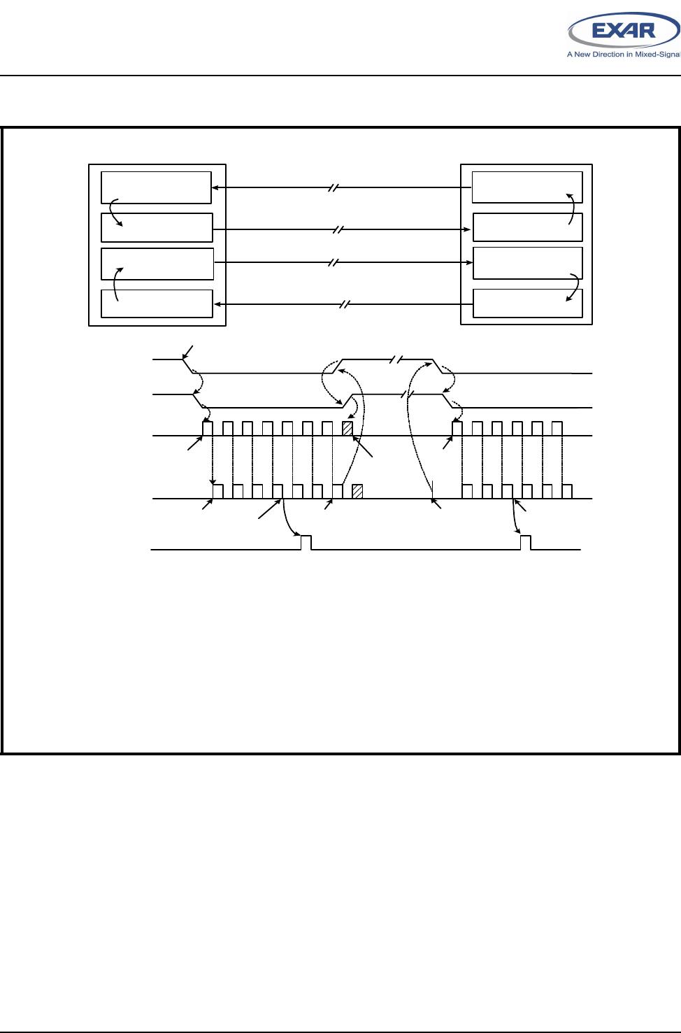
2.16 Auto CTS Flow Control
Automatic CTS flow control is used to prevent data overrun to the remote receiver FIFO. The CTS# input is
monitored to suspend/restart the local transmitter. The auto CTS flow control feature is selected to fit specific
application requirement (see Figure 10):
Enable auto CTS flow control using EFR bit-7.
If using the Auto CTS interrupt:
Enable CTS interrupt through IER bit-7 (after setting EFR bit-4). The UART issues an interrupt when the
CTS# pin is de-asserted (logic 1): ISR bit-5 will be set to 1, and UART will suspend transmission as soon as
the stop bit of the character in process is shifted out. Transmission is resumed after the CTS# input is re-
asserted (logic 0), indicating more data may be sent.
XR16C864
18
2.97V TO 5.5V QUAD UART WITH 128-BYTE FIFO
REV. 2.2.0
F
IGURE
10. A
UTO
RTS
AND
CTS F
LOW
C
ONTROL
O
PERATION
The local UART (UARTA) starts data transfer by asserting RTSA# (1). RTSA# is normally connected to CTSB# (2) of
remote UART (UARTB). CTSB# allows its transmitter to send data (3). TXB data arrives and fills UARTA receive FIFO
(4). When RXA data fills up to its receive FIFO trigger level, UARTA activates its RXA data ready interrupt (5) and con-
tinues to receive and put data into its FIFO. If interrupt service latency is long and data is not being unloaded, UARTA
monitors its receive data fill level to match the upper threshold of RTS delay and de-assert RTSA# (6). CTSB# follows
(7) and request UARTB transmitter to suspend data transfer. UARTB stops or finishes sending the data bits in its trans-
mit shift register (8). When receive FIFO data in UARTA is unloaded to match the lower threshold of RTS delay (9),
UARTA re-asserts RTSA# (10), CTSB# recognizes the change (11) and restarts its transmitter and data flow again until
next receive FIFO trigger (12). This same event applies to the reverse direction when UARTA sends data to UARTB
with RTSB# and CTSA# controlling the data flow.
RTSA# CTSB#
RXA TXB
Transmitter
Receiver FIFO
Trigger Reached
Auto RTS
Trigger Level
Auto CTS
Monitor
RTSA#
TXB
RXA FIFO
CTSB#
Remote UART
UARTB
Local UART
UARTA
ON
OFF
ON
Suspend
Restart
RTS High
Threshold
Data Starts
ON
OFF
ON
Assert RTS# to Begin
Transmission
1
2
3
4
5
6
7
Receive
Data
RTS Low
Threshold
9
10
11
Receiver FIFO
Trigger Reached
Auto RTS
Trigger Level
Transmitter
Auto CTS
Monitor
RTSB#CTSA#
RXBTXA
INTA
(RXA FIFO
Interrupt)
RX FIFO
Trigger Level
RX FIFO
Trigger Level
8
12
RTSCTS1

XR16C864IQ-F

Mfr. #:
Manufacturer:
MaxLinear
Description:
UART Interface IC UART
Lifecycle:
New from this manufacturer.
Delivery:
DHL FedEx Ups TNT EMS
Payment:
T/T Paypal Visa MoneyGram Western Union

Products related to this Datasheet