XR16C864
40
2.97V TO 5.5V QUAD UART WITH 128-BYTE FIFO
REV. 2.2.0
EFR[6]: Auto RTS Flow Control Enable
RTS# output may be used for hardware flow control by setting EFR bit-6 to logic 1. When Auto RTS is
selected, an interrupt will be generated when the receive FIFO is filled to the programmed trigger level and
RTS de-asserts to a logic 1 at the next upper trigger level/hysteresis level. RTS# will return to a logic 0 when
FIFO data falls below the next lower trigger level/hysteresis level. The RTS# output must be asserted (logic 0)
before the auto RTS can take effect. RTS# pin will function as a general purpose output when hardware flow
control is disabled.
Logic 0 = Automatic RTS flow control is disabled (default).
Logic 1 = Enable Automatic RTS flow control.
EFR[7]: Auto CTS Flow Control Enable
Automatic CTS Flow Control.
Logic 0 = Automatic CTS flow control is disabled (default).
Logic 1 = Enable Automatic CTS flow control. Data transmission stops when CTS# input de-asserts to logic
1. Data transmission resumes when CTS# returns to a logic 0.
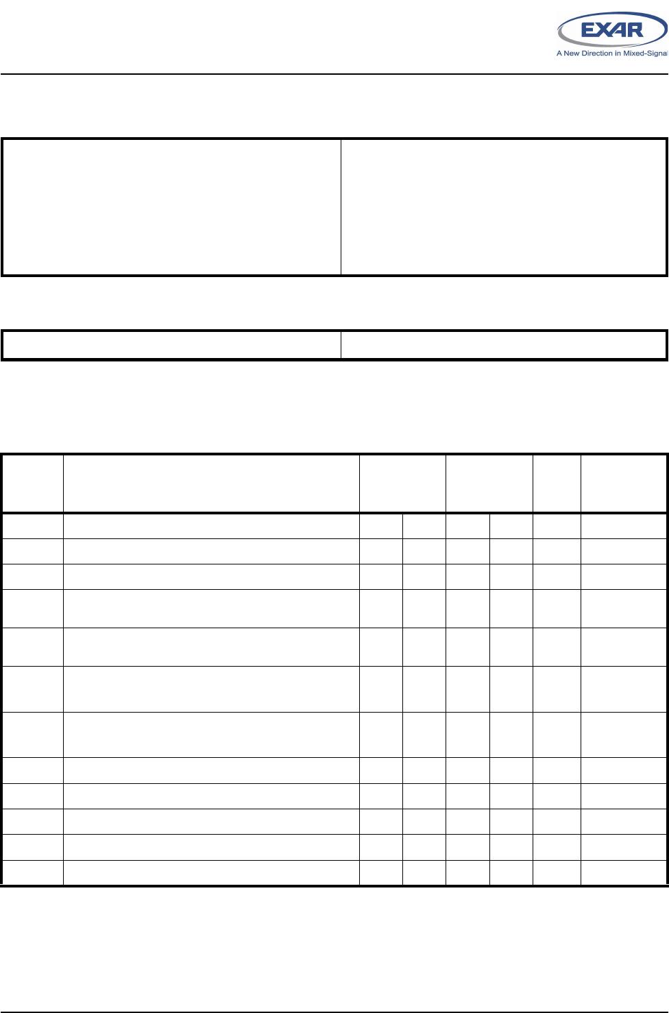
4.20 Software Flow Control Registers (XOFF1, XOFF2, XON1, XON2) - Read/Write
These registers are used as the programmable software flow control characters xoff1, xoff2, xon1, and xon2.
For more details, see
Table 7
.
4.21 FIFO Status Register (FSTAT) - Read/Write
The FIFO Status Register provides a status indication for each of the transmit and receive FIFO. These status
bits contain the inverted logic states of the TXRDY# A-D outputs and the (un-inverted) logic states of the
RXRDY# A-D outputs. The contents of the FSTAT register are placed on the data bus when the FSRS# pin (pin
76) is a logic 0. Also see FSRS# pin description.
FSTAT[3:0]: TXRDY# A-D Status Bits
Please see
Table 5
for the interpretation of the TXRDY# signals.
FSTAT[7:4]: RXRDY# A-D Status Bits
Please see
Table 5
for the interpretation of the RXRDY# signals.
XR16C864
41
REV. 2.2.0
2.97V TO 5.5V QUAD UART WITH 128-BYTE FIFO
T
ABLE
19: UART RESET CONDITIONS FOR CHANNELS A-D
REGISTERS RESET STATE
DLL Bits 7-0 = 0xXX
DLM Bits 7-0 = 0xXX
RHR Bits 7-0 = 0xXX
THR Bits 7-0 = 0xXX
IER Bits 7-0 = 0x00
FCR Bits 7-0 = 0x00
ISR Bits 7-0 = 0x01
LCR Bits 7-0 = 0x00
MCR Bits 7-0 = 0x00
LSR Bits 7-0 = 0x60
MSR Bits 3-0 = Logic 0
Bits 7-4 = Logic levels of the inputs inverted
SPR Bits 7-0 = 0xFF
EMSR Bits 7-0 = 0x00
FLVL Bits 7-0 = 0x00
TRG Bits 7-0 = 0x00
FC Bits 7-0 = 0x00
FCTR Bits 7-0 = 0x00
EFR Bits 7-0 = 0x00
XON1 Bits 7-0 = 0x00
XON2 Bits 7-0 = 0x00
XOFF1 Bits 7-0 = 0x00
XOFF2 Bits 7-0 = 0x00
FSTAT Bits 7-0 = 0xFF
I/O SIGNALS RESET STATE
TX Logic 1
IRTX Logic 0
RTS# Logic 1
DTR# Logic 1
RXRDY# Logic 1
TXRDY# Logic 0
INT XR16C864 = Three-State Condition
IRQ# Logic 1 (68 mode, INTSEL = 0)
XR16C864
42
2.97V TO 5.5V QUAD UART WITH 128-BYTE FIFO
REV. 2.2.0
ELECTRICAL CHARACTERISTICS
Test 1: The following inputs remain steady at VCC or GND state to minimize Sleep current: A0-A2, D0-D7, IOR#, IOW#,
CSA#, CSB#, CSC#, and CSD#. Also, RXA, RXB, RXC, and RXD inputs idle at logic 1 state while asleep.
ABSOLUTE MAXIMUM RATINGS
Power Supply Range 7 Volts
Voltage at Any Pin GND-0.3 V to 7 V
Operating Temperature
-40
o
to +85
o
C
Storage Temperature
-65
o
to +150
o
C
Package Dissipation 500 mW
TYPICAL PACKAGE THERMAL RESISTANCE DATA
(MARGIN OF ERROR: ± 15%)
Thermal Resistance (100-QFP)
theta-ja = 45
o
C/W, theta-jc = 12
o
C/W
DC ELECTRICAL CHARACTERISTICS
U
NLESS
OTHERWISE
NOTED
: TA=0
O
TO
70
O
C (-40
O
TO
+85
O
C
FOR
INDUSTRIAL
GRADE
PACKAGE
), V
CC
IS
2.97
TO
5.5V
S
YMBOL
P
ARAMETER
L
IMITS
3.3V
M
IN
M
AX
L
IMITS
5.0V
M
IN
M
AX
U
NITS
C
ONDITIONS
V
ILCK
Clock Input Low Level -0.3 0.6 -0.5 0.6 V
V
IHCK
Clock Input High Level 2.4 VCC 3.0 VCC V
V
IL
Input Low Voltage -0.3 0.8 -0.5 0.8 V
V
IH
Input High Voltage
(Devices with top mark date code of "DC YYWW" and older)
2.0 VCC 2.2 VCC V
V
IH
Input High Voltage
(Devices with top mark date code of "F2 YYWW" and newer)
2.0 5.5 2.2 5.5 V
V
OL
Output Low Voltage
0.4
0.4 V I
OL
= 6 mA
I
OL
= 4 mA
V
OH
Output High Voltage
2.0
2.4 V I
OH
= -6 mA
I
OH
= -1 mA
I
IL
Input Low Leakage Current ±10 ±10 uA
I
IH
Input High Leakage Current ±10 ±10 uA
C
IN
Input Pin Capacitance 5 5 pF
I
CC
Power Supply Current 3 6 mA
I
SLEEP
Sleep Current 100 200 uA See Test 1

XR16C864IQ-F

Mfr. #:
Manufacturer:
MaxLinear
Description:
UART Interface IC UART
Lifecycle:
New from this manufacturer.
Delivery:
DHL FedEx Ups TNT EMS
Payment:
T/T Paypal Visa MoneyGram Western Union

Products related to this Datasheet