DATASHEET
10BASE-T/100BASE-TX INTEGRATED PHYCEIVER WITH RMII INTERFACE
ICS1894-40
IDT®
10BASE-T/100BASE-TX INTEGRATED PHYCEIVER WITH RMII INTERFACE 1
ICS1894-40 REV K 022412
Description
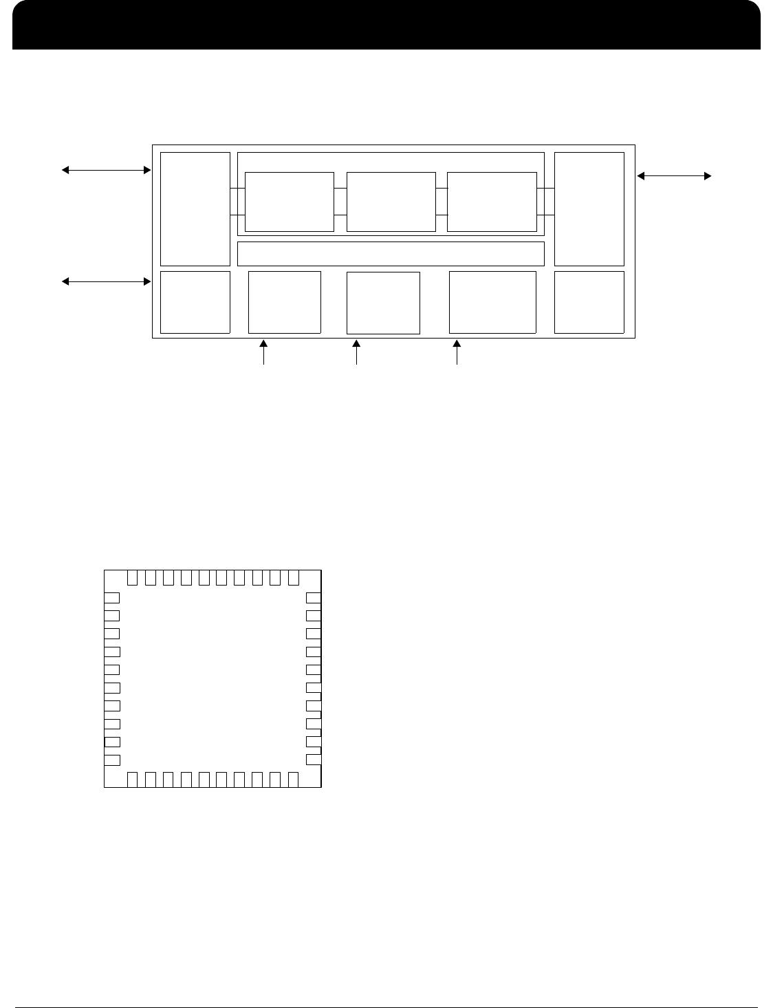
The ICS1894-40 is a low-power, physical-layer device
(PHY) that supports the ISO/IEC 10Base-T and
100Base-TX Carrier-Sense Multiple Access/Collision
Detection (CSMA/CD) Ethernet standards, ISO/IEC
8802.3. It is intended for RMII/MII, Node/Repeater
applications and includes the Auto-MDIX feature that
automatically corrects crossover errors in plant wiring.
The ICS1894-40 incorporates Digital-Signal Processing
(DSP) control in its Physical-Medium Dependent (PMD)
sub-layer. As a result, it can transmit and receive data on
unshielded twisted-pair (UTP) category 5 cables with
attenuation in excess of 24 dB at 100MHz.
The ICS1894-40 provides a Serial-Management Interface
for exchanging command and status information with a
Station-Management (STA) entity. The ICS1894-40
Media-Dependent Interface (MDI) can be configured to
provide either half-duplex or full-duplex operation at data
rates of 10 Mb/s or 100Mb/s.
In addition, the ICS1894-40 includes a programmable LED
and interrupt output function. The LED outputs can be
configured through registers to indicate the occurance of
certain events such as LINK, COLLISION, ACTIVITY, etc.
The purpose of the programmable interrupt output is to
notify the PHY controller device immediately when a certain
event happens instead of having the PHY controller
continuously poll the PHY. The events that could be used to
generate interrupts are: receiver error, Jabber, page
received, parallel detect fault, link partner acknowledge, link
status change, auto-negotiation complete, remote fault,
collision, etc.
The ICS1894-40 has deep power modes that can result in
significant power savings when the link is broken.
Applications: NIC cards, PC motherboards, switches,
routers, DSL and cable modems, game machines, printers,
network connected appliances, and industrial equipment.
Features
Supports category 5 cables and above with attenuation in
excess of 24dB at 100 MHz.
Single-chip, fully integrated PHY provides PCS, PMA,
PMD, and AUTONEG sub layers functions of IEEE
standard.
10Base-T and 100Base-TX IEEE 8802.3 compliant
MIIM (MDC/MDIO) management bus for PHY register
configuration
RMII interface support with external 50 MHz system clock
Single 3.3V power supply
Highly configurable, supports:
– Media Independent Interface (MII)
– Auto-Negotiation with Parallel detection
– Node applications, managed or unmanaged
– 10M or 100M full and half-duplex modes
– Loopback mode for Diagnostic Functions
Auto-MDI/MDIX crossover correction
Low-power CMOS (typically 300 mW)
Power-Down mode (typically 21mW)
Clock and crystal supported in MII mode
Programmable LEDs
Interrupt output pin
Fully integrated, DSP-based PMD includes:
– Adaptive equalization and baseline-wander
correction
– Transmit wave shaping and stream cipher
scrambler
– MLT-3 encoder and NRZ/NRZI encoder
Core power supply (3.3 V)
3.3 V/1.8 V VDDIO operation supported
Smart power control with deep power down feature
Available in 40-pin (6mm x 6mm) QFN package, Pb-free
Industrial Temp and Lead Free
Not recommended for new designs
— For full/half duplex RMII only interface support, please refer to ICS1894-43 datasheet.
— For full/half duplex MII only interface support, please refer to ICS1894-44 datasheet.
— ICS1894-43 and ICS1894-44 are pin-compatible with ICS1894-40.
ICS1894-40
10BASE-T/100BASE-TX INTEGRATED PHYCEIVER WITH RMII INTERFACE PHYCEIVER
IDT®
10BASE-T/100BASE-TX INTEGRATED PHYCEIVER WITH RMII INTERFACE 2
ICS1894-40 REV K 022412
Block Diagram
Pin Assignment
Clock Power LEDs and PHY
Address
Twisted-
Pair
Interface to
Magnetics
Modules and
RJ45
Connector
Integrated
Switch
MII
Extended
Register
Set
Interface
MUX
PCS
Framer
CRS/COL
Detection
Parallel to Serial
•4B/5B
Auto-
Negotiation
10Base-T
100Base-T
TP_PMD
•MLT-3
Stream Cipher
Adaptive Equalizer
Baseline Wander
Correction
PMA
Clock Recovery
Link Monitor
Signal Detection
Error Detection
Low-Jitter
Clock
Synthesizer
Configuration
and Status
10/100 MII/RMII
MAC
Interface
MII
Management
Interface
Smart Power
Control
Block
1
40-pin MLF
TP_AP
TP_BN
SI/LED4
NOD/RXER
ANSEL/RXCLK
RMII/RXDV
FDPX/RXD0
TXD3
P0/LED0
VDD
RESET_N
11
21
31
VSS
TP_AN
TP_BP
VDD
VDDD
AMDIX
VSS
MDIO
MDC
AMDIXRXD3
P3/RXD2
RXTR1RXD1
SPEED/TXCLK
TXER
TXD0
TXD1
TXD2
VDDIO REFOUT
REFIN
P1/LED1
P2/INT
P4/LED2
HWSW/CRS
REGPIN/COL
TCSR
TXEN
LED3
NLG40 Without Ground Connecting to
Thermal Pad
SPEED
1
40
-
pin MLF
TP_AP
TP_BN
SI/LED4
NOD/RXER
ANSEL/RXCLK
RMII/RXDV
FDPX/RXD0
TXD3
P0/LED0
VDD
RESET_N
11
21
31
VSS
TP_AN
TP_BP
VDD
VDDD
AMDIX
VSS
MDIO
MDC
AMDIXRXD3
P3/RXD2
RXTR1RXD1
SPEED/TXCLK
TXER
TXD0
TXD1
TXD2
VDDIO
REFOUT
REFIN
P1/ISO/LED1
P2/INT
P4/LED2
HWSW/CRS
REGPIN/COL
TCSR
TXEN
LED3
NLG40 Without Ground Connecting to
Thermal Pad
SPEED
ICS1894-40
10BASE-T/100BASE-TX INTEGRATED PHYCEIVER WITH RMII INTERFACE PHYCEIVER
IDT®
10BASE-T/100BASE-TX INTEGRATED PHYCEIVER WITH RMII INTERFACE 3
ICS1894-40 REV K 022412
Pin Descriptions
Pin
Number
Pin
Name
Pin
Type
Pin Description
1
AMDIX IN/Ipu AMDIX Enable
2 TP_AP AIO Twisted pair port A (for either transmit or receive) positive signal
3 TP_AN AIO Twisted pair port A (for either transmit or receive) negative signal
4 VSS Ground Connect to ground.
5 VDD Power 3.3V Power Supply
6 TP_BN AIO Twisted pair port B (for either transmit or receive) negative signal
7 TP_BP AIO Twisted pair port B (for either transmit or receive) positive signal
8 VDD Power 3.3V Power Supply
9 TCSR AIO Transmit Current bias pin, connected to Vdd and ground via two resistors.
10 VSS Ground Connect to ground.
11 RESET_N Input Hardware reset for the whole chip (active low)
12 P2/INT IO/Ipd PHY address Bit 2 as input (during power on reset and hardware reset)
Interrupt output as output (default active low, can be programmed to active high)
13 MDIO IO Management Data Input/Output
14 MDC Input Management Data Clock
15 VDDIO Power 3.3 V IO Power Supply.
16 HWSW/
CRS
IO/Ipd Hardware/Software control for phy speed as input (during power on reset and
hardware reset) and CRS output in MII mode.
17 Regpin/
COL
IO/Ipd Full register access enable as input (during power on reset and hardware reset) and
COL output in MII mode
18 AMDIX/RXD3 IO/Ipu AMDIX hardware enable as input (during power on reset and hardware reset)
Receive data Bit 3 as output in MII mode
19 P3/RXD2 IO/Ipd PHY address Bit 3 as input (during power on reset and hardware reset)
Receive data Bit 2 as output in MII mode
20 RXTRI/
RXD1
IO/Ipd RX isolate enable (during power on reset and hardware reset)
Received data Bit 1 as output in both RMII and MII modes
21 SI/LED4 IO/Ipd MII/SI mode select as input (during power on reset and hardware reset) and
LED #4 as output
22 FDPX/
RXD0
IO/Ipu Full duplex enable (during power on reset and hardware reset)
Received data Bit 0 as output in both RMII and MII modes.
23 RMII/RXDV IO/Ipd RMII/MII select as input (during power on reset and hardware reset)
Receive data valid in MII mode and CRS_DV in RMII mode as output
24 SPEED Ipu 10/100M input select. 1 = 100M mode, 0 = 10M mode.
25 TXER IN TXER Input
26 ANSEL/
RXCLK9
IO/Ipu Auto-negotiation enable(during power on reset and hardware reset)
Receive clock as output in MII mode
27 NOD/
RXER
IO/Ipd Node/repeater select (during power on reset and hardware reset)
Receive error as output in MII mode

1894K-40LFT

Mfr. #:
Manufacturer:
IDT
Description:
Ethernet ICs 3.3V 10/100 PHY RMII
Lifecycle:
New from this manufacturer.
Delivery:
DHL FedEx Ups TNT EMS
Payment:
T/T Paypal Visa MoneyGram Western Union

Products related to this Datasheet