ICS1894-40
10BASE-T/100BASE-TX INTEGRATED PHYCEIVER WITH RMII INTERFACE PHYCEIVER
IDT®
10BASE-T/100BASE-TX INTEGRATED PHYCEIVER WITH RMII INTERFACE 40
ICS1894-40 REV K 022412
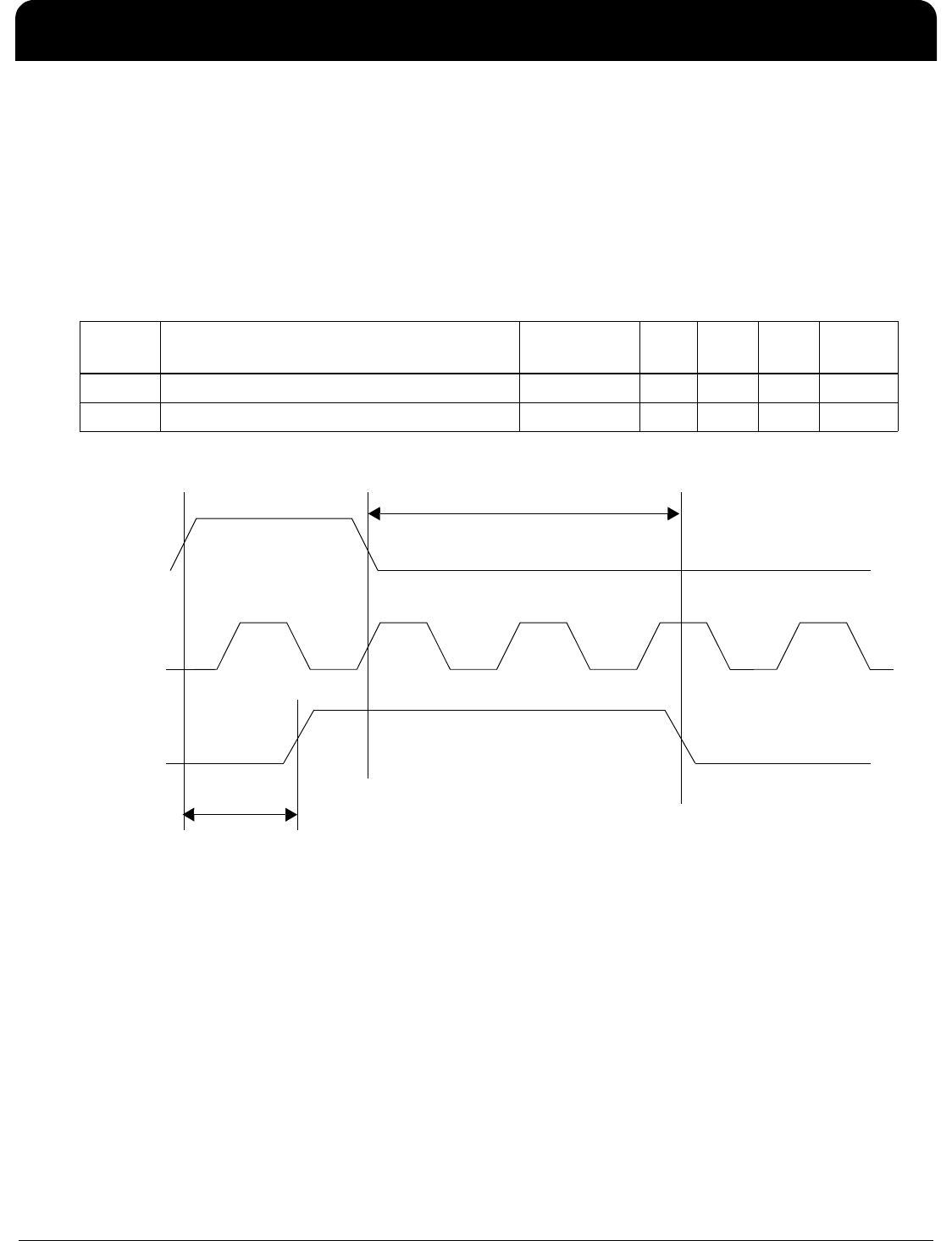
100M / MII Media Independent Interface: Transmit Latency
The table below lists the significant time periods for the MII/100 Stream Interface transmit latency. The time periods
consist of timings of signals on the following pins:
• TXEN
• TXCLK
• TXD (that is, TXD[3:0])
• TP_TX (that is, TP_TXP and TP_TXN)
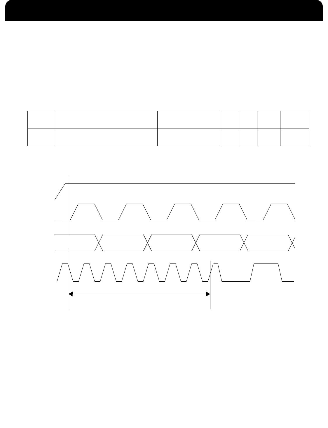
The MII/100M Stream Interface Transmit Latency Timing Diagram shows the timing diagram for the time periods.
† The IEEE maximum is 18 bit times.
MII/100M Stream Interface Transmit Latency Timing Diagram
Time
Period
Parameter Conditions Min. Typ. Max. Units
t1 TXEN Sampled to MDI Output of First
Bit of /J/ †
MII mode – 2.8 3 Bit times
TXEN
TXCLK
TXD
TP_TX
†
†
Shown
unscrambled.
t1
Preamble /K/Preamble /J/