ICS1894-40
10BASE-T/100BASE-TX INTEGRATED PHYCEIVER WITH RMII INTERFACE PHYCEIVER
IDT®
10BASE-T/100BASE-TX INTEGRATED PHYCEIVER WITH RMII INTERFACE 35
ICS1894-40 REV K 022412
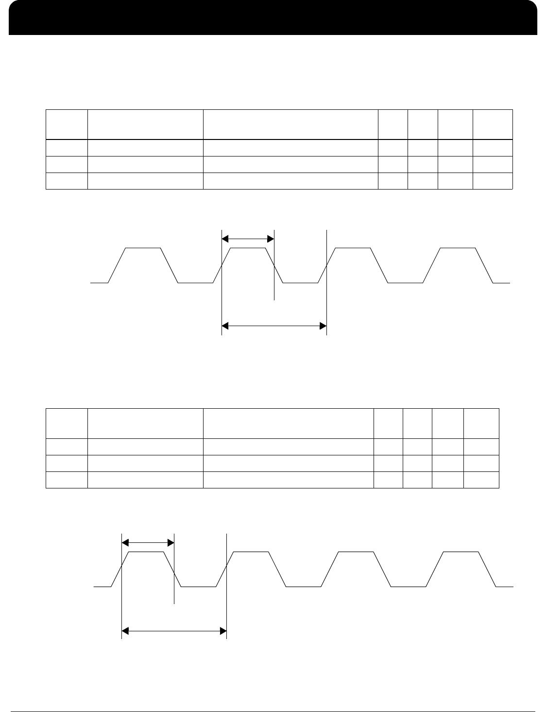
100M MII: Synchronous Transmit Timing
The table below lists the significant time periods for the 100M MII Interface synchronous transmit timing. The time
periods consist of timings of signals on the following pins:
• TXCLK
• TXD[3:0]
• TXEN
• TXER
The 100M MII/100M Stream Interface Synchronous Transmit Timing Diagram figure shows the timing diagram for
the time periods.
100M MII/100M Stream Interface Synchronous Transmit Timing Diagram
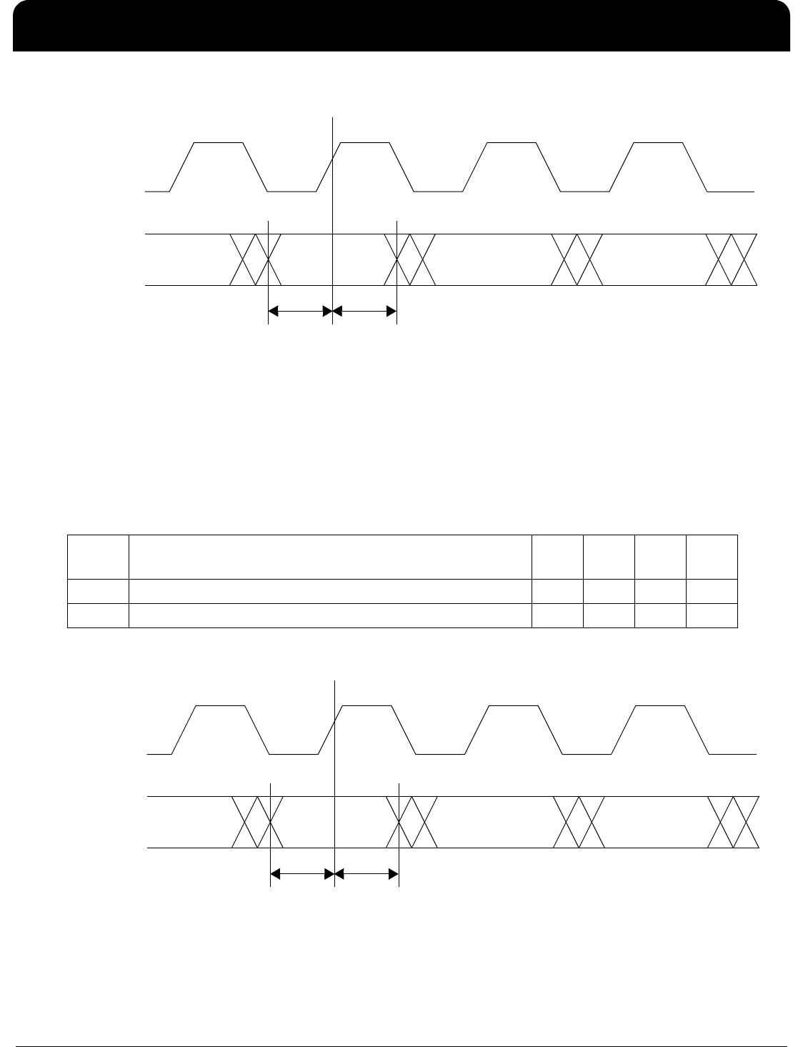
10M MII: Synchronous Transmit Timing
The table below lists the significant time periods for the 10M MII synchronous transmit timing. The time periods
consist of timings of signals on the following pins:
• TXCLK
• TXD[3:0]
• TXEN
• TXER
The 10M MII Synchronous Transmit Timing Diagram figure shows the timing diagram for the time periods.
Time
Period
Parameter Conditions Min. Typ. Max. Units
t1 TXD[3:0], TXEN, TXER Setup to TXCLK Rise – 15 – – ns
t2 TXD[3:0], TXEN, TXER Hold after TXCLK Rise – 0 – – ns
t1 t2
TXCLK
TXD[3:0]
TXEN
TXER
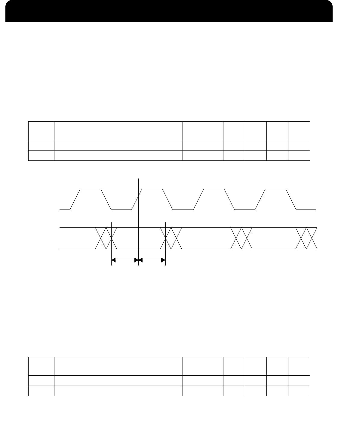
Time
Period
Parameter Conditions Min. Typ. Max. Units
t1 TXD[3:0], TXEN, TXER Setup to TXCLK Rise – 375 – – ns
t2 TXD[3:0], TXEN, TXER Hold after TXCLK Rise – 0 – – ns