ICS1894-40
10BASE-T/100BASE-TX INTEGRATED PHYCEIVER WITH RMII INTERFACE PHYCEIVER
IDT®
10BASE-T/100BASE-TX INTEGRATED PHYCEIVER WITH RMII INTERFACE 7
ICS1894-40 REV K 022412
If auto-negotiation is not supported or the ICS1894-40 link
partner is forced to bypass auto-negotiation, the
ICS1894-40 sets its operating mode by observing the signal
at its receiver. This is known as parallel detection, and
allows the ICS1894-40 to establish link by listening for a
fixed signal protocol in the absence of auto-negotiation
advertisement protocol.
MII Management (MIIM) Interface
The ICS1894-40 supports the IEEE 802.3 MII Management
Interface, also known as the Management Data Input /
Output (MDIO) Interface. This interface allows upper-layer
devices to monitor and control the state of the ICS1894-40.
An external device with MIIM capability is used to read the
PHY status and/or configure the PHY settings. Additional
details on the MIIM interface can be found in Clause
22.2.4.5 of the IEEE 802.3u Specification.
The MIIM interface consists of the following:
A physical connection that incorporates the clock line
(MDC) and the data line (MDIO).
A specific protocol that operates across the
aforementioned physical connection that allows an
external controller to communicate with one or more
ICS1894-40 devices. Each ICS1894-40 device is
assigned a PHY address that is set by the P[4:0]
strapping pins
An internal addressable set of thirty-one 8-bit MDIO
registers. Register [0:6] are required, and their functions
are defined by the IEEE 802.3u Specification. The
additional registers are provided for expanded
functionality.
The ICS1894-40 supports MIIM in both MII mode and RMII
mode.
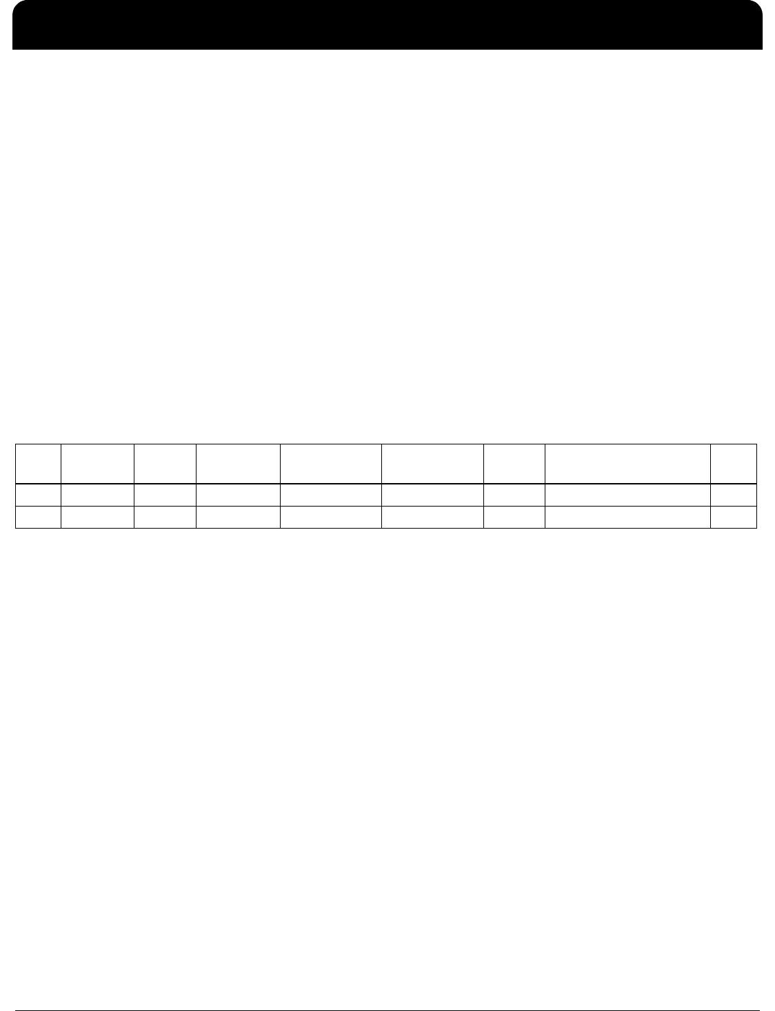
The following table shows the MII Management frame
format for the ICS1894-40.
MII Management Frame Format
Interrupt (INT)
P2/INT (pin 12) is an optional interrupt signal that is used to
inform the external controller that there has been a status
update in the ICS1894-40 PHY register. Register 23 shows
the status of the various interrupts while register 22 controls
the enabling/disabling of the interrupts.
MII Data Interface
The Media Independent Interface (MII) is specified in
Clause 22 of the IEEE 802.3u Specification. It provides a
common interface between physical layer and MAC layer
devices, and has the following key characteristics:
Supports 10Mbps and 100Mbps data rates.
Uses a 25MHz reference clock, sourced by the PHY.
Provides independent 4-bit wide (nibble) transmit and
receive data paths.
Contains two distinct groups of signals: one for
transmission and the other for reception.
The ICS1894-40 is configured for MII mode upon power-up
or hardware reset with the following:
A 25MHz crystal connected to REFIN, REFOUT (pins 7,
36), or an external 25MHz clock source (oscillator)
connected to REFIN
Preamble Start of
Frame
Read/Write
OP Code
PHY Address
Bits [4:0]
REG Address
Bits [4:0]
TA Data Bits
[15:0]
Idle
Read 32 1’s 01 10 1AAAA RRRRR Z0 DDDDDDDD_DDDDDDDD Z
Write 32 1’s 01 01 00AAA RRRRR 10 DDDDDDDD_DDDDDDDD Z
ICS1894-40
10BASE-T/100BASE-TX INTEGRATED PHYCEIVER WITH RMII INTERFACE PHYCEIVER
IDT®
10BASE-T/100BASE-TX INTEGRATED PHYCEIVER WITH RMII INTERFACE 8
ICS1894-40 REV K 022412
MII Signal Definition
The following table describes the MII signals. Refer to Clause 22 of the IEEE 802.3u Specification for detailed information.
Transmit Clock (TXCLK)
TXCLK is sourced by the PHY. It is a continuous clock that
provides the timing reference for TXEN and TXD[3:0].
TXCLK is 2.5MHz for 10Mbps operation and 25MHz for
100Mbps operation.
Transmit Enable (TXEN)
TXEN indicates the MAC is presenting nibbles on TXD[3:0]
for transmission. It is asserted synchronously with the first
nibble of the preamble and remains asserted while all
nibbles to be transmitted are presented on the MII, and is
negated prior to the first TXCLK following the final nibble of
a frame. TXEN transitions synchronously with respect to
TXCLK.
Transmit Data (TXD[3:0])
TXD[3:0] transitions synchronously with respect to TXCLK.
When TXEN is asserted, TXD[3:0] are accepted for
transmission by the PHY. TXD[3:0] is ”00” to indicate idle
when TXEN is de-asserted. Values other than “00” on
TXD[3:0] while TXEN is de-asserted are ignored by the
PHY.
Receive Clock (RXCLK)
RXCLK provides the timing reference for RXDV, RXD[3:0],
and RXER.
In 10Mbps mode, RXCLK is recovered from the line while
carrier is active. RXCLK is derived from the PHY’s
reference clock when the line is idle, or link is down.
In 100Mbps mode, RXCLK is continuously recovered
from the line. If link is down, RXCLK is derived from the
PHY’s reference clock.
RXCLK is 2.5MHz for 10Mbps operation and 25MHz for
100Mbps operation.
Receive Data Valid (RXDV)
RXDV is driven by the PHY to indicate that the PHY is
presenting recovered and decoded nibbles on RXD[3:0].
In 10Mbps mode, RXDV is asserted with the first nibble of
the SFD (Start of Frame Delimiter), and remains asserted
until the end of the frame.
In 100Mbps mode, RXDV is asserted from the first nibble
of the preamble to the last nibble of the frame.
RXDV transitions synchronously with respect to RXCLK.
Receive Data (RXD[3:0])
RXD[3:0] transitions synchronously with respect to RXC.
For each clock period in which RXDV is asserted, RXD[3:0]
transfers a nibble of recovered data from the PHY.
MII Signal Name Direction
(with respect to PHY,
ICS1894-40 signal)
Direction
(with respect to MAC)
Description
TXCLK Output Input Transmit Clock
(2.5MHz for 10Mbps; 25MHz for 100Mbps)
TXEN Input Output Transmit Enable
TXD[3:0] Input Output Transmit Data [3:0]
RXCLK Output Input Receive Clock
(2.5MHz for 10Mbps; 25MHz for 100Mbps)
RXDV Output Input Receive Data Valid
RXD[3:0] Output Input Receive Data [3:0]
RXER Output Input, or (not required) Receive Error
CRS Output Input Carrier Sense
COL Output Input Collision Detection
ICS1894-40
10BASE-T/100BASE-TX INTEGRATED PHYCEIVER WITH RMII INTERFACE PHYCEIVER
IDT®
10BASE-T/100BASE-TX INTEGRATED PHYCEIVER WITH RMII INTERFACE 9
ICS1894-40 REV K 022412
Receive Error (RXER)
RXER is asserted for one or more RXCLK periods to
indicate that an error (e.g. a coding error or any error that a
PHY is capable of detecting, and that may otherwise be
undetectable by the MAC sub-layer) was detected
somewhere in the frame presently being transferred from
the PHY. RXER transitions synchronously with respect to
RXC. While RXDV is de-asserted, RXER has no effect on
the MAC.
Carrier Sense (CRS)
CRS is asserted and de-asserted as follows:
In 10Mbps mode, CRS assertion is based on the
reception of valid preambles. CRS de-assertion is based
on the reception of an end-of-frame (EOF) marker.
In 100Mbps mode, CRS is asserted when a
start-of-stream delimiter, or /J/K symbol pair is detected.
CRS is deasserted when an end-of-stream delimiter, or
/T/R symbol pair is detected. Additionally, the PMA layer
de-asserts CRS if IDLE symbols are received without
/T/R.
Collision (COL)
COL is asserted in half-duplex mode whenever the
transmitter and receiver are simultaneously active on the
line. This is used to inform the MAC that a collision has
occurred during its transmission to the PHY.
COL transitions asynchronously with respect to TXCLK and
RXCLK.
Reduced MII (RMII) Data Interface
The Reduced Media Independent Interface (RMII) specifies
a low pin count Media Independent Interface (MII). It
provides a common interface between physical layer and
MAC layer devices, and has the following key
characteristics:
Supports 10Mbps and 100Mbps data rates.
Uses a single 50MHz reference clock provided by the
MAC or the system board.
Provides independent 2-bit wide (di-bit) transmit and
receive data paths.
Contains two distinct groups of signals: one for
transmission and the other for reception.
In RMII mode, a 50 MHz reference clock is connected to
REFIN(pin 30).

1894K-40LFT

Mfr. #:
Manufacturer:
IDT
Description:
Ethernet ICs 3.3V 10/100 PHY RMII
Lifecycle:
New from this manufacturer.
Delivery:
DHL FedEx Ups TNT EMS
Payment:
T/T Paypal Visa MoneyGram Western Union

Products related to this Datasheet