ICS1894-40
10BASE-T/100BASE-TX INTEGRATED PHYCEIVER WITH RMII INTERFACE PHYCEIVER
IDT®
10BASE-T/100BASE-TX INTEGRATED PHYCEIVER WITH RMII INTERFACE 37
ICS1894-40 REV K 022412
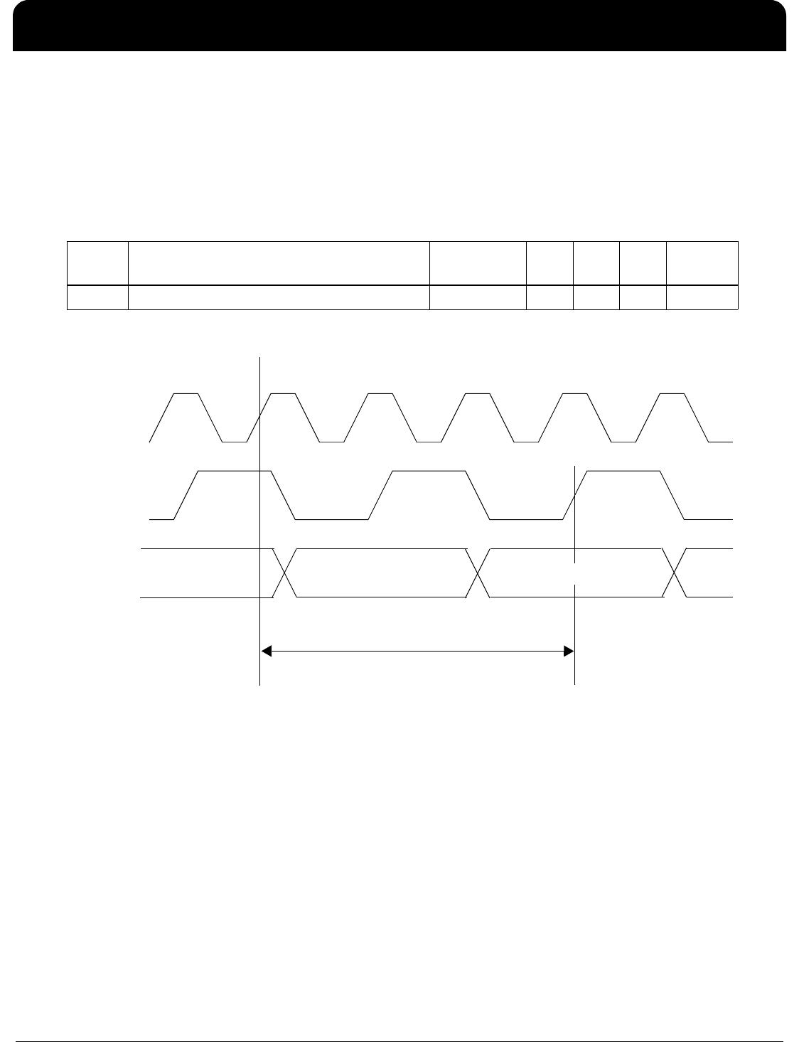
MII Management Interface Timing
The table below lists the significant time periods for the MII Management Interface timing (which consists of timings
of signals on the MDC and MDIO pins). The MII Management Interface Timing Diagram figure shows the timing
diagram for the time periods.
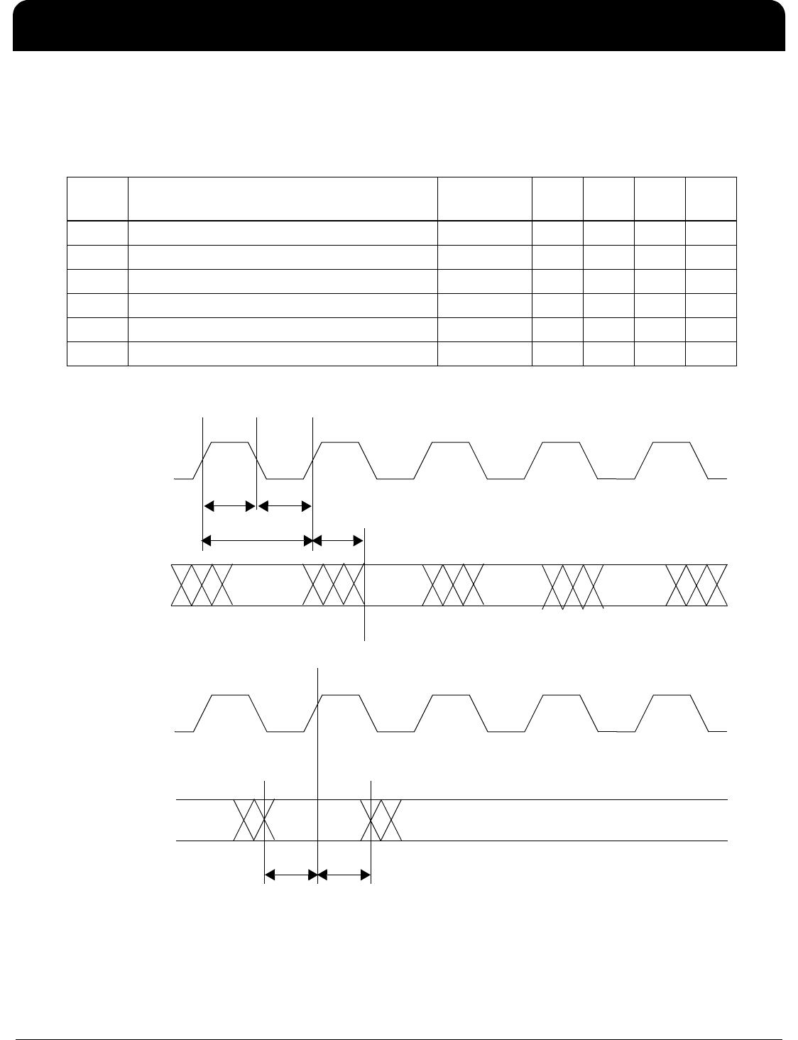
MII Management Interface Timing Diagram
Time
Period
Parameter Conditions Min. Typ. Max. Units
t1 MDC Minimum High Time – 160 – – ns
t2 MDC Minimum Low Time – 160 – – ns
t3 MDC Period – 400 – – ns
t4 MDC Rise Time to MDIO Valid – 0 – 300 ns
t5 MDIO Setup Time to MDC – 10 – – ns
t6 MDIO Hold Time after MDC – 10 – – ns
MDC
MDIO
(Output)
MDC
MDIO
(Input)
t1 t2
t3 t4
t5 t6