ICS1894-40
10BASE-T/100BASE-TX INTEGRATED PHYCEIVER WITH RMII INTERFACE PHYCEIVER
IDT®
10BASE-T/100BASE-TX INTEGRATED PHYCEIVER WITH RMII INTERFACE 46
ICS1894-40 REV K 022412
Reset: Hardware Reset and Power-Down
The table below lists the significant time periods for the hardware reset and power-down reset. The time periods
consist of timings of signals on the following pins:
REF_IN
RESETn
TXCLK
The Hardware Reset and Power-Down Timing Diagram shows the timing diagram for the time periods.
Hardware Reset and Power-Down Timing Diagram
Time
Period
Parameter Conditions Min. Typ. Max
.
Units
t1 RESETn Active to Device Isolation and Initialization 60 ns
t2 Minimum RESETn Pulse Width 200 ns
t3 RESETn Released to TXCLK Valid 35 500 ms
REF_IN
RESETn
t1
t2 t3
TXCLK Valid
Power
Consumption
(AC only)
ICS1894-40
10BASE-T/100BASE-TX INTEGRATED PHYCEIVER WITH RMII INTERFACE PHYCEIVER
IDT®
10BASE-T/100BASE-TX INTEGRATED PHYCEIVER WITH RMII INTERFACE 47
ICS1894-40 REV K 022412
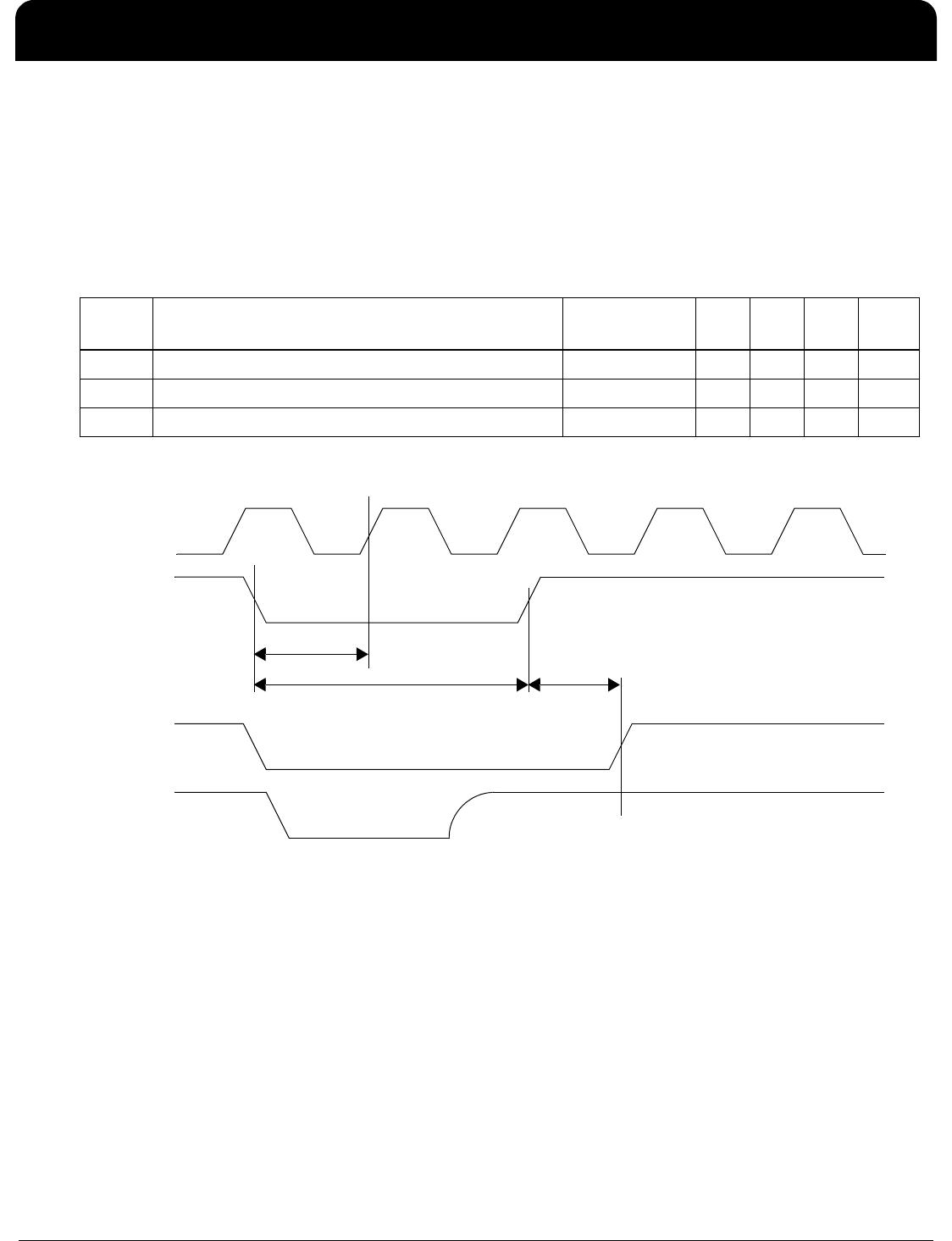
10Base-T: Heartbeat Timing (SQE)
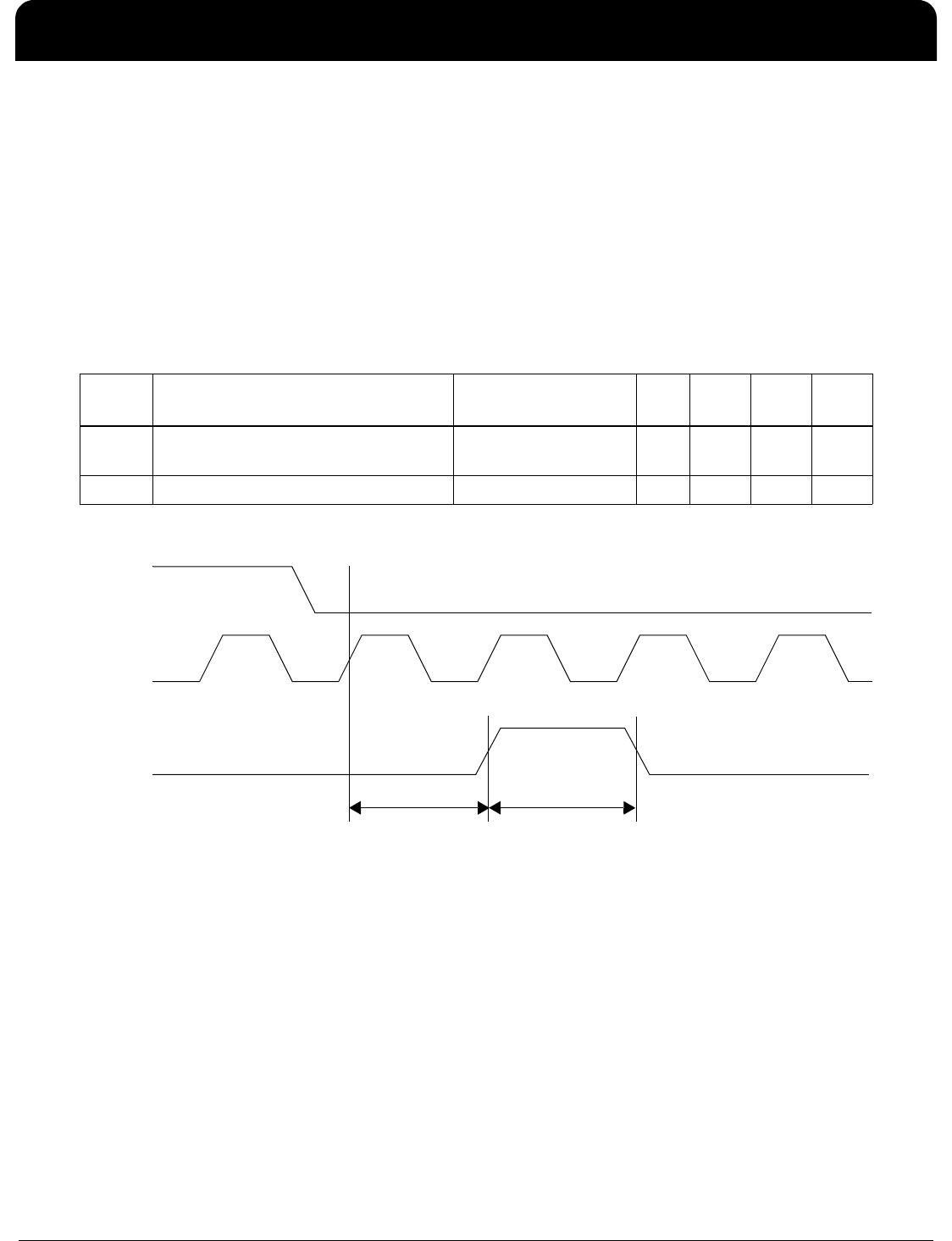
The table below lists the significant time periods for the 10Base-T heartbeat (that is, the Signal Quality Error). The
time periods consist of timings of signals on the following pins:
TXEN
TXCLK
COL
The 10Base-T Heartbeat (SQE) Timing Diagram shows the timing diagram for the time periods.
Note:
1. For more information on 10Base-T SQE operations, see the section “10Base-T Operation: SQE Test”.
2. In 10Base-T mode, one bit time = 100 ns.
10Base-T Heartbeat (SQE) Timing Diagram
Time
Period
Parameter Conditions Min. Typ. Max. Units
t1 COL Heartbeat Assertion Delay from
TXEN De-Assertion
10Base-T Half Duplex 850 1500 ns
t2 COL Heartbeat Assertion Duration 10Base-T Half Duplex 1000 1500 ns
t2t1
TXEN
TXCLK
COL
ICS1894-40
10BASE-T/100BASE-TX INTEGRATED PHYCEIVER WITH RMII INTERFACE PHYCEIVER
IDT®
10BASE-T/100BASE-TX INTEGRATED PHYCEIVER WITH RMII INTERFACE 48
ICS1894-40 REV K 022412
10Base-T: Jabber Timing
The table below lists the significant time periods for the 10Base-T jabber. The time periods consist of timings of
signals on the following pins:
TXEN
TP_TX (that is, TP_TXP and TP_TXN)
COL
The 10Base-T Jabber Timing Diagram shows the timing diagram for the time periods.
Note: For more information on 10Base-T jabber operations, see the section, “10Base-T Operation: Jabber”.
10Base-T Jabber Timing Diagram
Time
Period
Parameter Conditions Min. Typ. Max. Units
t1 Jabber Activation Time 10Base-T Half Duplex 20 35 ms
t2 Jabber De-Activation Time 10Base-T Half Duplex 300 325 ms
TXEN
TP_TX
COL
t1
t2

1894K-40LFT

Mfr. #:
Manufacturer:
IDT
Description:
Ethernet ICs 3.3V 10/100 PHY RMII
Lifecycle:
New from this manufacturer.
Delivery:
DHL FedEx Ups TNT EMS
Payment:
T/T Paypal Visa MoneyGram Western Union

Products related to this Datasheet