Tsi721 Datasheet 19 April 4, 2016
Integrated Device Technology
2.3 Pinlist
For a list-based version of Tsi721’s pin to signal mapping, see the Tsi721 Ballmap and Pinlist.
2.4 PCIe Signals
Table 2: PCIe Signals
Name Pin Type Description
PCTP[3:0]
PCTN[3:0]
PCIE_O Differential transmit data for the PCIe port.
PCRP[3:0]
PCRN[3:0]
PCIE_I Differential receive data for the PCIe port.
PCCLKP
PCCLKN
DIFF_I PCIe reference clock input.
When in PCIe common clock mode (CLKMOD pin is high, see the “Clocking”
chapter in the Tsi721 User Manual), PCCLKP/N requires a clock frequency of
100 MHz.
When in PCIe non-common clock mode (CLKMOD pin is low), PCCLKP/N
requires a clock frequency as selected by CLKSEL[1:0], and must have the
same clock frequency as REFCLKP/N.
PCRSTOn IO It is an output for normal operation and an input during scan test mode.
As an asynchronous active-low reset output, this pin is low when the following
occurs:
The PCIe port detects hot reset
The PCIe port is DL_DOWN
Tsi721 Datasheet 20 April 4, 2016
Integrated Device Technology
2.5 S-RIO Signals
2.6 General Signals
Table 3: S-RIO Signals
Name Pin Type Description
a
a. For information on S-RIO signals that are used for power-up purposes only, see Power-up Signals.
SRTP[3:0]
SRTN[3:0]
SRIO_O Differential transmit data for the S-RIO port.
SRRP[3:0]
SRRN[3:0]
SRIO_I Differential receive data for the S-RIO port.
SRRSTOn IO It is an output for normal operation and an input during scan test mode.
As an asynchronous active-low reset output, this pin is low when four
consecutive S-RIO reset symbols are received, and SELF_RST is set to 1 in the
RapidIO PLM Port Implementation Specific Control Register
MECS IO-PD Asynchronous S-RIO Multicast Event Control Symbol (MECS). Its direction is
controlled by the MECS_O bit in the Device Control Register.
As an input, a rising or falling edge triggers an S-RIO MECS to be sent on the
S-RIO link. Use the RIO_PLM_SP0_MECS_FWD.SUBSCRIPTION/MULT_CS
and RIO_EM_MECS_TRIG_EN.CMD_EN to select the CMD field that should be
set with the MECS. Multiple MECSs with different CMD fields can be generated
by setting these fields appropriately.
As an output, this signal is toggled when an S-RIO MECS is received. Only a
single MECS CMD value should be selected to toggle the MECS input. Set the
RIO_EM_MECS_CAP_EN.CMD_EN to select the CMD value to be propagated
to the MECS pin. Note: Only 1 bit should be enabled in CMD_EN.
Table 4: General Signals
Name Pin Type Description
RSTn I-PU Fundamental reset (device reset).Assertion of this signal resets all logic inside
the Tsi721.
REFCLKP
REFCLKN
DIFF_I S-RIO reference clock input. REFCLK requires a clock frequency as selected by
CLKSEL[1:0].
Tsi721 Datasheet 21 April 4, 2016
Integrated Device Technology
2.7 I2C Signals
The I2C Interface is used for the following:
As a master, downloading configuration from EEPROM
As a master, allowing the PCIe root complex or the S-RIO host to configure other I2C expansion devices
As a slave, exposing internal register space to an I2C master (Note: To be used for lab debug or another master-driven
initialization).
2.8 JTAG and Test Interface Signals
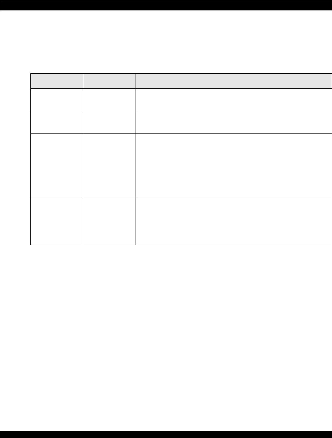
Table 5: I
2
C Signals
Name Pin Type Description
a
a. For information on I2C signals that are used for power-up purposes only, see Power-up Signals.
I2C_SCL IO-OD Serial clock for the I2C Interface with a maximum frequency of 100 kHz.
I2C_SDA IO-OD Serial data for the I2C Interface.
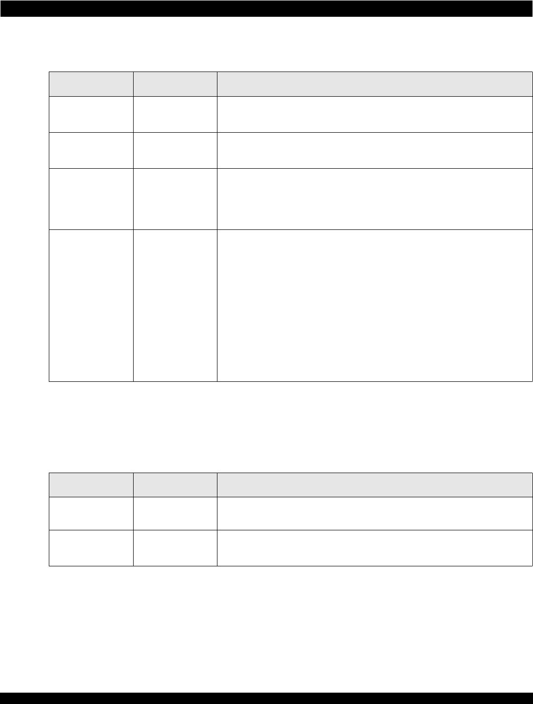
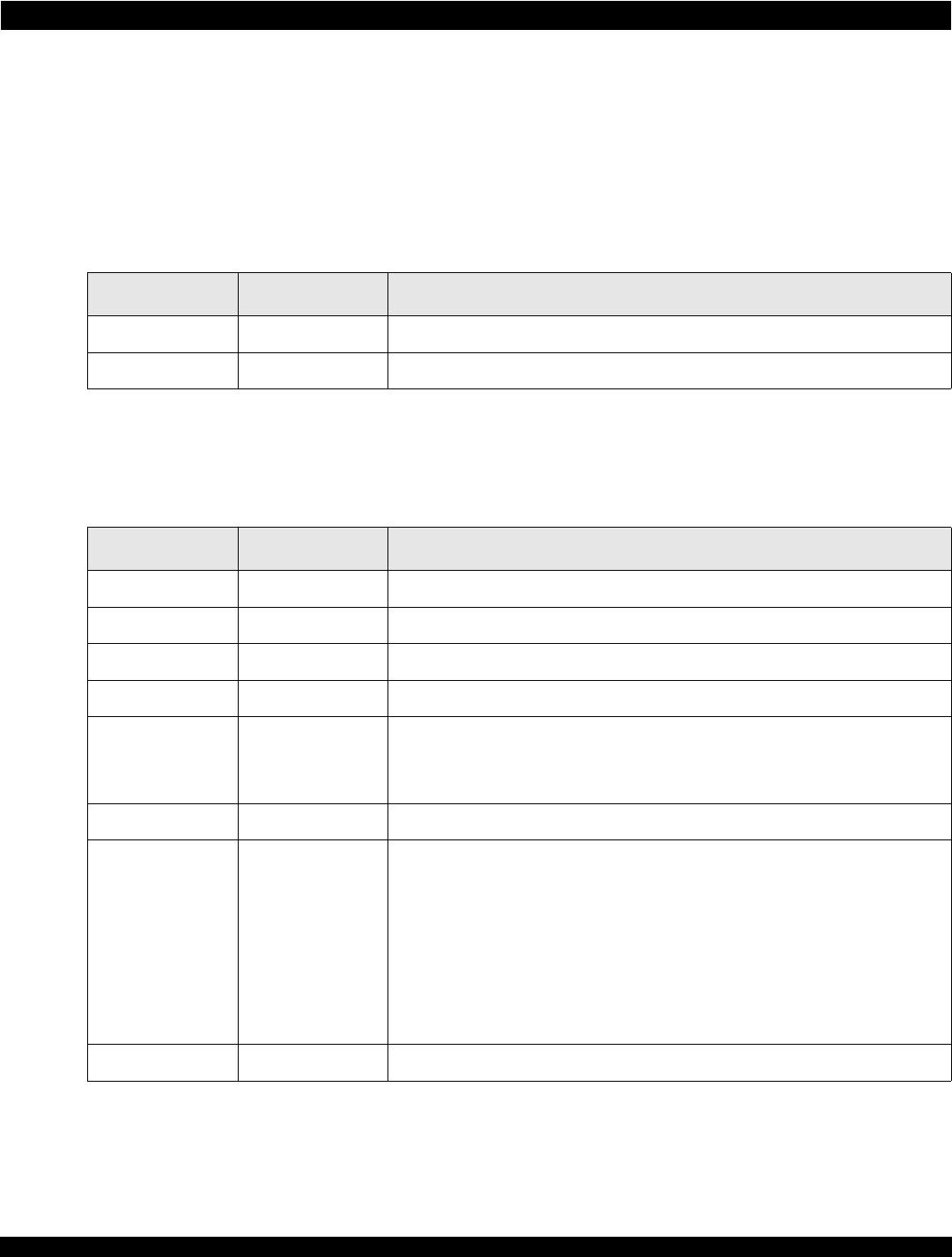
Table 6: JTAG Interface Signals
Name Pin Type Description
TCK I-PD IEEE 1149.1/1149.6 test access port. Clock input.
TDI I-PU IEEE 1149.1/1149.6 test access port. Serial data input
TDO O IEEE 1149.1/1149.6 test access port. Serial data output
TMS I-PU IEEE 1149.1/1149.6 test access port. Test mode select
TRSTn I-PU IEEE 1149.1/1149.6 test access port. Reset input.
This input must be asserted during the assertion of RSTn. Thereafter, it can be
left in either state.
TEST_ON I-PD Test mode pin. Tie low or NC for normal operation.
TEST_BCE I-PU Boundary scan compatibility enabled pin. This input aids 1149.6 testing. It must
be tied to VDDIO (or NC as there is internal pull up in pad) during normal
operation of the device.
0 = JTAG chain includes SerDes registers. SerDes registers are accessible to
external JTAG pins. Used during ATE and lab debug of SerDes registers through
an external JTAG Controller.
1 = JTAG chain does not include SerDes registers. SerDes register are
accessible through the internal register bus for BAR 0 access.
TEST_BIDIR_CTL I-PU Test mode pin. Tie high or NC for normal operation.

TSI721A1-16GILV

Mfr. #:
Manufacturer:
IDT
Description:
PCI Interface IC PCIe-to-Rapid IO Bridge
Lifecycle:
New from this manufacturer.
Delivery:
DHL FedEx Ups TNT EMS
Payment:
T/T Paypal Visa MoneyGram Western Union