Tsi721 Datasheet 48 April 4, 2016
Integrated Device Technology
3.7.4.2 Explanatory Note on Level II Transmitter and Receiver Specifications
AC electrical specifications are provided for transmitters and receivers. The parameters for the AC electrical specifications are
guided by the OIF CEI Electrical and Jitter Inter-operability agreement for CEI-6G-SR and CEI-6G-LR.
OIF CEI-6G-SR and CEI-6G-LR have similar application goals to S-RIO, as described in Section 10.1, “Level II Application
Goals.” The goal of this standard is that electrical designs for S-RIO can reuse electrical designs for OIF CEI-6G, suitably
modified for applications at the baud intervals and runs described herein.
3.7.4.3 Level II Electrical Specifications
The electrical interface is based on high speed, low voltage logic with nominal differential impedance of 100 Ohm. Connections
are point-to-point balanced differential pair and signaling is unidirectional.
3.7.4.3.1 Level II Transmitter Characteristics
Level II LP-Serial transmitter electrical and timing specifications are stated in the text and tables of this section.
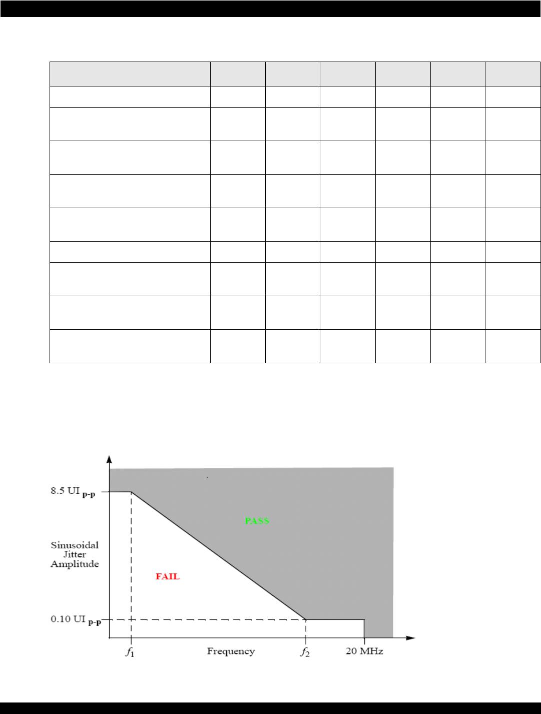
The differential return loss must be better than A0 from f0 to f1 and better than
A0 + Slope*log10(f/f1)
Where f is the frequency from f1 to f2 (see section 8.5.11, Figure 8-12 of the RapidIO Specification (Rev. 2.1). Differential
return loss is measured at compliance points T and R. If AC coupling is used, then all components (internal or external) are to
be included in this requirement. The reference impedance for the differential return loss measurements is 100 Ohm.
Common mode return loss measurement must be better than -6dB between a minimum frequency of 100 MHz and a
maximum frequency of 0.75 times the baud rate. The reference impedance for the common mode return loss is 25 Ohm.
The Tsi721 satisfies the specification requirement that the 20%-80% rise/fall time of the transmitter, as measured at the
transmitter output, in each case has a minimum value 30 ps.
Similarly, the timing skew at the output of an LP-Serial transmitter between the two signals that comprise a differential pair
does not exceed 10 ps at 5.0.