Tsi721 Datasheet 40 April 4, 2016
Integrated Device Technology
Each signal swings between the voltages VHIGH and VLOW where:
VHIGH > VLOW
The differential voltage, VDIFF is defined as:
VDIFF = VD+ - VD-
where VD+ is the voltage on the positive conductor and VD- is the voltage on the negative conductor of a differential
transmission line. VDIFF represents either the differential output signal of the transmitter, VOD, or the differential input signal of
the receiver, VID where:
VOD = VTD - VTD
and
VID = VRD - VRD
The common mode voltage, VCM, is defined as the average or mean voltage present on the same differential pair. Therefore:
VCM = | VD+ + VD- | / 2
The maximum value, or the peak-to-peak differential voltage, is calculated on a per unit interval and is defined as:
VDIFFp-p = 2 x max | VD+ - VD- |
because the differential signal ranges from VD+ - VD- to -(VD+ - VD-)
To illustrate these definitions using real values, consider the case of a CML (Current Mode Logic) transmitter and each of its
outputs, TD and TD_N, has a swing that goes between VHIGH = 2.5V and VLOW = 2.0V, inclusive. Using these values the
common mode voltage is calculated to be 2.25 V and the single-ended peak voltage swing of the signals TD and TD_N is
500 mVpp. The differential output signal ranges between 500 mV and -500 mV, inclusive. therefore the peak-to-peak
differential voltage is 1000 mVppd.
Tsi721 Datasheet 41 April 4, 2016
Integrated Device Technology
3.7.3.3 1.25 Gbps, 2.5 Gbps, and 3.125 Gbps LP-Serial Links
This section explains the requirements for Level I RapidIO LP-Serial short and long run electrical interfaces of nominal baud
rates of 1.25, 2.5, and 3.125 Gbps using NRZ coding (thus, 1 bit per symbol at the electrical level). The Tsi721’s SerDes meet
all of the requirements listed below. The electrical interface is based on a high speed, low voltage logic with a nominal
differential impedance of 100 Ohm. Connections are point-to-point balanced differential pair and signaling is unidirectional.
The level of links defined in this section are identical to those defined in the RapidIO Interconnect Specification (Revision 2.1),
1x/4x LP-Serial Electrical Specification.
3.7.3.4 Equalization
With the use of high speed serial links, the interconnect media will cause degradation of the signal at the receiver. Effects such
as Inter-Symbol Interference (ISI) or data dependent jitter are produced. This loss can be large enough to degrade the eye
opening at the receiver beyond what is allowed in the specification. To negate a portion of these effects, equalization can be
used in the transmitter and/or receiver, but it is not required at baud rates less than 3.125 Gbps.
3.7.3.5 Explanatory Note on Level I Transmitter and Receiver Specifications
AC electrical specifications are provided for the transmitter and receiver. Long run and short run interfaces at three baud rates
are described.
The parameters for the AC electrical specifications are guided by the XAUI electrical interface specified in Clause 47 of IEEE
802.3ae-2002.[1] The goal of this standard is that electrical designs for Level I electrical designs can reuse XAUI, suitably
modified for applications at the baud intervals and runs described herein.
3.7.3.6 Level I Electrical Specification
3.7.3.6.1 Level I Transmitter Characteristics
Level I LP-Serial transmitter electrical and timing specifications are stated in the text and tables of this section. The differential
return loss, S11, of the transmitter in each case must be better than:
-10 dB for (Baud Frequency) / 10 < Freq(f) < 625 MHz, and
-10 dB + 10log(f/625 MHz) dB for 625 MHz <= Freq(f) <= Baud Frequency
The reference impedance for the differential return loss measurements is 100 Ohm resistive. Differential return loss includes
contributions from on-chip circuitry, chip packaging and any off-chip components related to the driver. The output impedance
requirement applies to all valid output levels.
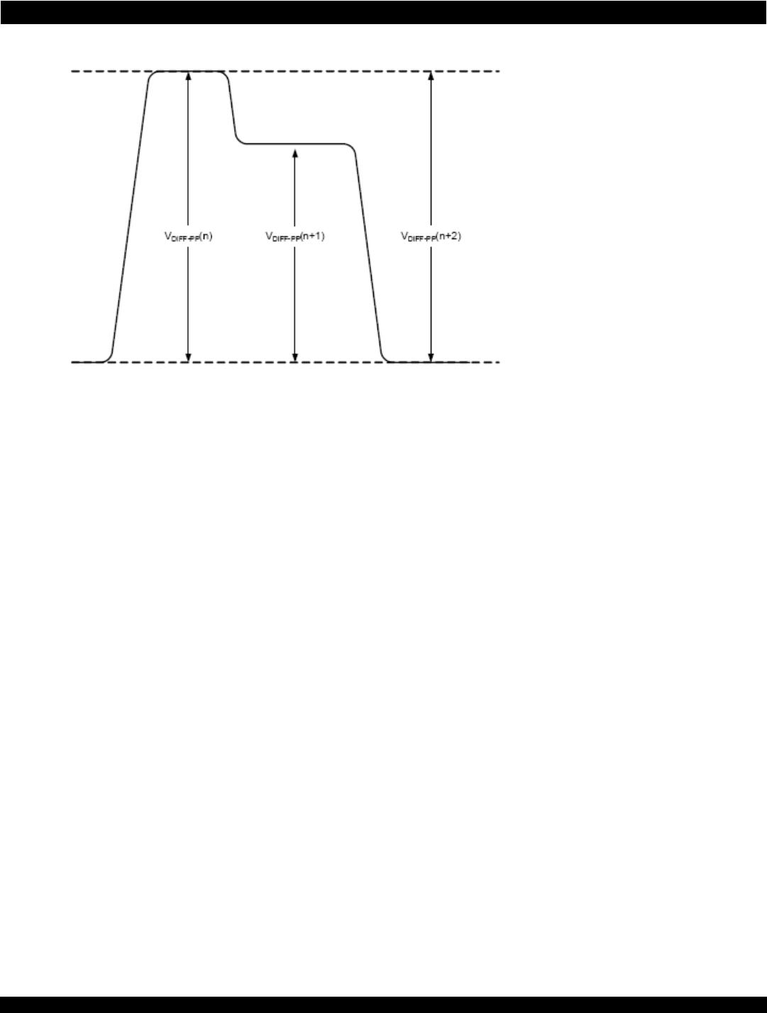
The Tsi721 satisfies the specification requirement that the 20%-80% rise/fall time of the transmitter, as measured at the
transmitter output, in each case has a minimum value 60 ps.
Similarly, the timing skew at the output of an LP-Serial transmitter between the two signals that comprise a differential pair
does not exceed 25 ps at 1.25 Gbps, 20 ps at 2.5 Gbps, and 15 ps at 3.125 Gbps.
Tsi721 Datasheet 42 April 4, 2016
Integrated Device Technology
3.7.3.6.2 Level I Short Run Transmitter Specifications
1. For all Load Types: R_Rdin = 100 Ohm +/- 20 Ohm.
2. Load Type 0 with min. T_Vdiff, AC-coupling or floating load.
3. It is suggested that T_SCC22 be -6 dB to be compatible with Level II transmitter requirements.
4. It is suggested that T_Ncm be limited to 5% of T_Vdiff to be compatible with Level II transmitter requirements.
Table 20: Level I Short Run Transmitter AC Timing Specifications
Symbol Characteristic Reference Minimum Typical Maximum Units
T_Baud Baud rate Section 9.4.1.2 1.25 - 3.125 Gbps
V
O
Absolute output voltage Section 9.4.1.3 -0.40 - 2.30 Volts
T_Vdiff Output differential voltage
(into floating load Rload = 100 Ohm)
Section 9.4.1.3 500 - 1000 mVppd
T_Rd Differential resistance Section 9.4.1.5 80 100 120 Ohm
T_tr, T_tf Recommended output rise and fall
times (20% to 80%)
Section 9.4.1.4 60 - - ps
T_SDD22 Differential output return loss
(T_baud/10 <
f < T_baud/2)
Section 9.4.1.6 - - - dB
Differential output return loss
(T_baud/10 <
f < T_baud/2)
---dB
T_TCC22 Common mode return loss
(625 MHz <
f < T_baud)
Section 9.4.1.6 - - Note 3 dB
T_Ncm Transmitter common mode noise
1
- - Note 4 mVppd
T_Vcm Output common mode voltage Load Type 0
2
0-2.1V
S
MO
Multiple output skew, N < 4 Section 9.4.1.7 - - 1000 ps
S
MO
Multiple output skew, N > 4 Section 9.4.1.7 - - 2UI + 1000 ps
UI Unit interval - 80 - 800 ps

TSI721A1-16GILV

Mfr. #:
Manufacturer:
IDT
Description:
PCI Interface IC PCIe-to-Rapid IO Bridge
Lifecycle:
New from this manufacturer.
Delivery:
DHL FedEx Ups TNT EMS
Payment:
T/T Paypal Visa MoneyGram Western Union