By Sharp Microelectronics 297
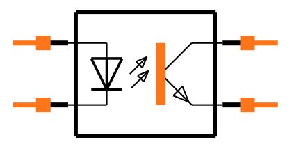
The PC817 is an Optocoupler or Optoisolator device, also known as an optocoupler isolator. It is a semiconductor component used for electrical isolation, usually consisting of a light-emitting diode (LED) and a photosensitive converter (phototransistor).
PC817 optocoupler is widely used in signal transmission between computer terminals, thyristor system equipment, measuring instruments, copiers, automatic ticket sales, household appliances (such as fans, heaters, etc.), and thoroughly connects its front end to the load. Isolation is used to improve safety, reduce circuit interference, and simplify circuit design.
Basic working principle of PC817:
•At the input of PC817, there is an LED, which is usually a red or infrared LED. When the appropriate forward voltage is applied between the two pins of the LED (usually by connecting a current limiting resistor), the LED turns on and current begins to flow through the LED.
•Physical isolation between the LED and the phototransistor ensures that there is no direct electrical connection between the input circuit and the output circuit. Therefore, the signal transmission between input and output is carried by light, not by current.
•The photoconverter is located at the output of the PC817 and is usually a phototransistor. When the LED emits light, the light strikes the sensitive part of the phototransistor. The light-sensitive element (usually a photoresistor or photodiode) within a phototransistor causes a change in resistance or current when it is illuminated and responds.
•When the LED is turned on and emits light, the light shines on the phototransistor, causing changes in the photosensitive element. This change can be converted into an output voltage or current signal, thereby achieving photoelectric conversion of the input signal. The output signals can be connected to external circuits to perform desired control or data transfer operations.
Ⅰ.Main parameters of PC817
•High isolation voltage: 5000V (effective value)
•Current transfer ratio: 50% (minimum)
•Peak forward current (ICE max): 1A
•Forward current (ICEO): 50mA
•Reverse voltage: 6V
•Collector emitter voltage: 35V
•Emitter-collector voltage: 6V
•Power consumption: 70mW
•Collector current: 50mA
•Collector power consumption: 150mW
•Operating temperature: -30℃~+100℃
•Total power consumption: 200mW
•Collector-emitter saturation voltage: 0.1V (typ.)
•Current transmission ratio: 50% ~ 600%
•Cutoff frequency: 80kHz
Ⅱ.Package type of PC817
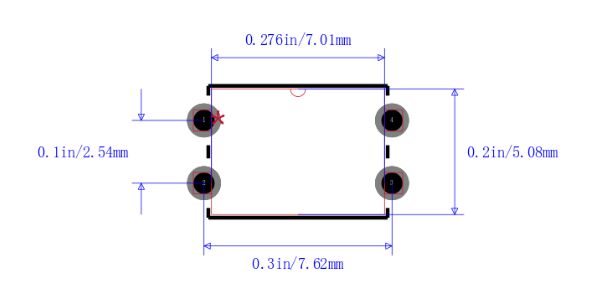
PC817 comes in a variety of package types, the most common of which are DIP (Dual In-Line Package) and SMD (Surface Mount Device Package) packages.
1.DIP package: DIP package is a dual in-line package consisting of two pins connected in parallel. This package form is generally suitable for socket-type applications. The PC817 can be easily inserted into a standard socket or soldered to a circuit board. For DIP packaging, the common PC817 model is PC817N.
2.SMD packaging: SMD packaging is a surface mount device packaging and is suitable for SMT (Surface Mount Technology) applications. These packages are typically smaller than DIP packages and are suitable for high-density circuit board designs. PC817 models in SMD packages usually have "X" or "SM" as part of the model name. For example, PC817X series.
Ⅲ.Test method of PC817
1.LED test
Test the forward voltage (VF) and forward current (IF) of the LED: Use a suitable detection device, such as a digital multimeter or LED tester, to detect the forward voltage and forward current of the light-emitting diode. To determine whether these values comply with the PC817 standard.
Activate the LED: By connecting an appropriate current limiting resistor, forward current is introduced into the LED to ensure that the LED emits light normally.
2.Electrical characteristics test
Test current transfer ratio (CTR): CTR refers to the ratio of the input LED current to the output phototransistor current. Use a suitable detection circuit to detect the CTR value to ensure that it meets the technical requirements.
Test bandwidth and response time: For higher response speed requirements, the frequency band and response time of PC817 can be tested to ensure compliance with the requirements.
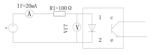
3.Forward voltage drop test
As shown in the figure, pins 1 and 2 are loaded, IF=20mA, use a multimeter to test that the voltage drop Vf of pins 1 and 2 is less than or equal to 1.4V.
4.Photosensitive converter test
Test the isolation performance of the optocoupler: Use an appropriate voltage to measure the insulation resistance between the input and output. Due to the extremely high isolation requirements of the optocoupler, sufficient voltage should be provided at these two endpoints.
Test the response of a photoconverter: Use a light source (usually an infrared light source) to illuminate the photosensitive portion of the photoconverter and measure the output current or voltage response. If the results are as expected, then the response is as expected.
5.Isolation voltage test
Measure the isolation voltage of the PC817: With an appropriate test circuit, measure the isolation voltage between the input and output of the PC817 to ensure it meets the application requirements.
6.Saturation pressure drop test
Pins 1 and 2 are loaded with f=20mA, and pins 3 and 4 are loaded with c=1mA. Use a multimeter to test that the voltage drop at pins 3 and 4, Vce, is less than or equal to 0.2V.
.jpg)
7.Environmental testing
Environmental adaptability test: If PC817 needs to work in specific environments such as high temperature, low temperature, and high humidity, PC817 needs to be subjected to appropriate environmental adaptability tests to ensure the stability and working performance of PC817.
Ⅳ.Application fields of PC817
1. Signal conversion: PC817 can be used to transfer digital or analog signals from one circuit to another circuit to achieve signal conversion function. This is useful in sensor applications, data acquisition and control systems.
2. Motor control: In motor drive and control circuits, PC817 can be used to isolate control signals to ensure safe isolation between motor control circuits and high-voltage or high-current motor circuits.
3. Electrical isolation: One of the most important applications of PC817 is to work in circuits that require electrical isolation. It isolates signals from one circuit to another to prevent the propagation of current, voltage, or noise interference. This is very common in fields such as industrial automation, power systems, and instrumentation.
4. Switch control: It can be used as an optical coupling switch to switch external circuits by controlling LEDs. This usage is common in logic level translation, circuit protection, and remote control applications.
5. Communication equipment: In communication equipment, PC817 can be used in optical coupling transceivers to isolate and transmit signals to reduce electrical noise and improve communication quality.
6. Power management: PC817 can be used in power management circuits to isolate power and control circuits to improve the stability and safety of the power system.
7. Medical equipment: In medical equipment, PC817 can be used to isolate measurement and control signals to ensure the safety and reliability of medical equipment.
8. Automotive electronics: In the field of automotive electronics, PC817 can be used to isolate control signals to ensure the stability and safety of vehicle electronic systems.
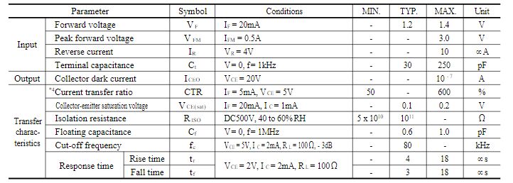
Ⅴ.Absolute Maximum Ratings and Electro-optical Characteristics
•Absolute Maximum Ratings(Ta=25 ̊C)

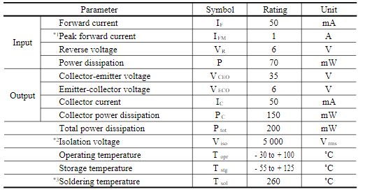
•Electro-optical Characteristics(Ta=25 ̊C)
Ⅵ. Alternative model of PC817
•PC847: The PC847 is an alternative model to the PC817 and generally has similar features but may have different parameters such as isolation voltage or current transfer ratio.
•PC827: PC827 is one of the replacement models of PC817, with similar functions and performance, but may differ in some parameters. Typically used in similar applications.
•MOC302X Series: The MOC302X Series is a group of optocoupler devices manufactured by Fairchild Semiconductor (now ON Semiconductor) for use in relay driving and AC voltage control applications. They can replace PC817 in some applications.
•TLP181: TLP181 is an optocoupler device produced by Toshiba and is commonly used in electrical isolation and signal transmission applications. It can be used as an alternative to PC817.
•SFH620A: SFH620A is an optocoupler device manufactured by Infineon, used in electrical isolation and control applications, and can also replace PC817 in some cases.
Frequently Asked Questions
1.How to connect and use PC817 correctly?
First, confirm the pin assignments of the PC817. A typical PC817 DIP package includes 4 pins, divided into two input pins (LED) and two output pins (phototransistor). Connect the input signal to the PC817's LED. Typically, the anode is connected to the positive electrode and the cathode is connected to the negative electrode. This is to make the LED work properly and ensure that current flows in the LED. The output signal will be passed out from the Collector and Emitter pins of the PC817's phototransistor.
2.What is the response time of PC817?
PC817: Typically has a response time in the range of several 10μs.
3.Does PC817 have fixed gain or adjustable gain function?
PC817 is an optical coupling device. Generally, it does not have fixed gain or adjustable gain functions. Its main function is to transmit input signals from one line to another to achieve electrical isolation.
4.How is the isolation between input and output achieved in PC817?
The electrical isolation of PC817 adopts the principle of optical insulation, using the light between the light-emitting LED and the photosensitive transistor to transmit signals, ensuring the electrical insulation of PC817. This insulator plays an important role in high-voltage and low-voltage circuits, and can effectively suppress noise and prevent circuits from external interference.