By NXP 479
BC857 is a typical PNP type bipolar transistor. It is an electronic component used for amplification, switching and current control in electronic circuits.
BC857 is a PNP bipolar transistor, where "P" stands for positive polarity, which means that its collector is P-type material, and the base and emitter are N-type materials. BC857 is commonly used in amplifier circuits, especially low-power amplifiers. It can also be used as a switch to control the flow of electricity in a circuit.
Ⅰ.Basic characteristics of BC857
•Amplification characteristics: BC857 is commonly used in small signal amplifier applications. Its Current Gain is a key parameter, usually represented by hfe or beta value. This represents the gain between the base current and the collector current.
•Ideally suited for automatic insertion
•Cutoff frequency: In BC857, the cutoff rate means that the signal of BC857 will not be amplified at higher frequencies. This frequency is generally related to the physical properties of the transistor and circuit design.
•Temperature Characteristics: BC857 performance may vary with temperature, so data sheets typically contain performance curves and parameters over temperature.
•For Switching and AF Amplifier Applications
Ⅱ.Main parameters of BC857
•Installation style:SMD/SMT
•Transistor polarity: PNP
•Maximum collector-emitter voltage VCEO: 50 V
•Collector-base voltage VCBO: 50 V
•Emitter-base voltage VEBO:5 V
•Collector-emitter saturation voltage: 650 mV
•Maximum DC collector current: 100 mA
•Pd-Power dissipation: 250 mW
•Minimum operating temperature: -55 C
•Maximum operating temperature: +150 C
•Collector continuous current: 100 mA
•Number of pins: 3
•Package type: SOT-23
•Noise factor (NF), maximum: 10dB
•DC current gain hfe, minimum value: 220
•DC current gain hFE: 220
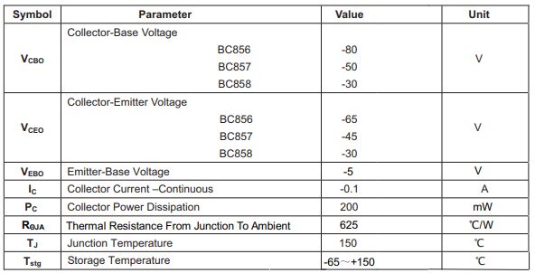
Ⅲ.MAXIMUM RATINGS and ELECTRICAL CHARACTERISTICS of the BC857
1.MAXIMUM RATINGS(Ta=25℃ unless otherwise noted)
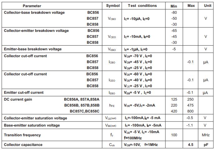
2.ELECTRICAL CHARACTERISTICS (TD=25℃ unless otherwise specified)
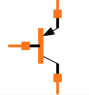
IV.Pin configuration of BC857
1.Collector, C: Usually the first pin of BC857, used to connect to the collector terminal in the circuit. This is an important pin of the transistor that accepts current.
2.Base, B: Usually the second pin of BC857, used to connect to the base terminal in the circuit. Controlling the current at the base controls the flow of current between the collector and emitter, thereby controlling the operating state of the transistor.
3.Emitter, E: Usually the third pin of BC857, used to connect to the emitter terminal in the circuit. Current flows from the emitter, controlled by the base, to the collector.
Ⅴ.Correctly connect the BC857 transistor
1.Identify the pins: First, look at the BC857 transistor's package or data sheet to determine its pin configuration. Generally, the pin configuration of BC857 is Collector, C, Base, B and Emitter, E. Make sure you identify these pins correctly.
2.Connect the collector: Connect the collector (C) to the desired collector terminal in the circuit. This is usually where the connection is made to the power source or load.
3.Connect the emitter: Connect the emitter (E) to the desired emitter terminal in the circuit. The current will flow from here.
4.Connect the base: Connect the base (B) to the desired base terminal in the circuit. By controlling the current on the base, the working state of BC857 can be controlled.
5.Add a current limiting resistor: Usually, in order to limit the base current, you need to add an appropriate current limiting resistor between the base and the power supply. This helps ensure that the current in the transistor does not exceed its rating. The value of the current limiting resistor will vary depending on your application and supply voltage, and can be calculated based on the current amplification factor (hfe or beta value) provided in the BC857's data sheet.
6.Connect other circuit components: In order to achieve the required functions, other resistors, capacitors or other components can be connected to the BC857.
7.Power supply: Finally, connect the power supply to the appropriate location to provide the required voltage.
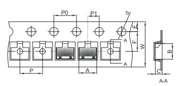
Ⅵ.BC857 packaging
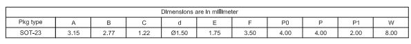
1.SOT-23 Embossed Carrier Tape
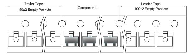
2.SOT-23 Tape Leader and Trailer
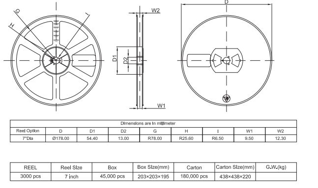
3.SOT-23 Reel
Ⅶ.Typical applications of BC857
1.Small signal amplifier: BC857 is widely used in small signal amplifier circuits, especially low power consumption and low noise amplifiers. It can be used to amplify weak input signals, such as those obtained from sensors or audio sources.
2.Power management: BC857 can be used in power management circuits such as current sources, current regulators and battery chargers. It helps control current and voltage to ensure power supply stability and efficiency.
3.Signal conditioner: BC857 can be used as a stabilizer to control the amplitude and frequency of the signal in the circuit. This is key to regulating the performance of electronic devices.
4.Switching circuit: Since BC857 can work at low voltage and has fast switching speed, it is suitable for switching circuits. It can be used for switching power supplies, battery management, and various control applications.
5.Current amplifier: Due to the amplification characteristics of BC857, it can also be used as a current amplifier. Use a voltage amplifier circuit to convert the input current into a larger output current.
6.Analog switch: BC857 can also be used as an analog switch to switch analog signal paths or connect different circuit components to achieve different circuit functions.
Frequently Asked Questions
1.What are the alternative models of BC857?
Alternative models of BC857 are: 2N3906, BC807, BC327, BC327, MPSA56
2.What is the difference between BC857 and other commonly used bipolar transistors?
BC857 is a PNP transistor, while other commonly used bipolar transistors such as 2N3904 are NPN type. This means that the BC857's current flows in the opposite direction than an NPN transistor. In BC857, current flows from base to emitter and from emitter to collector, whereas in NPN transistor, current flows in the opposite direction. Different models of bipolar transistors have different pin configurations, so you need to pay attention when connecting and using them. The BC857's pins are typically collector, base, and emitter, while other models may have different pin configurations.
3.What are the temperature characteristics of BC857? How will the performance change at different temperatures?
Temperature changes may affect the amplification characteristics of the BC857, such as the amplification factor (hfe or beta value). Generally speaking, an increase in temperature may result in a decrease in magnification. This means that at different temperatures, the BC857 may amplify the input signal differently. Increased temperature may also affect the BC857's cutoff frequency, especially at high temperatures. This can lead to performance degradation in high frequency applications. Temperature may also affect the BC857's current and voltage characteristics. For example, at high temperatures, a transistor's saturation current and maximum voltage ratings may change.
4.How to use BC857 as a switch in a circuit?
Determine the base current, which is the key to controlling the BC857 switching state. By controlling the current at the base of the BC857, the current flow between the collector and emitter can be controlled. Typically, a current limiting resistor needs to be added to ensure that the base current does not exceed the BC857's maximum rating. The circuit that controls the base current is connected to the BC857's base pin (Base, B). This circuit usually includes a resistor to limit the base current, and the base current can be adjusted by controlling the value of the resistor. Connect the collector (C) of the BC857 to the positive terminal of the power supply or the load, and connect the emitter (Emitter, E) to the negative terminal of the power supply or the load. When the current on the base reaches a sufficient value, the BC857 will be in a saturated state, and current can flow from the collector to the emitter, achieving a conductive state. When the current on the base is lower than a certain threshold, the BC857 will be in a cut-off state, and current cannot flow from the collector to the emitter, achieving a disconnected state.