By NXP Semiconductors 118
The TJA1051T/3/1J is an automotive-grade CAN chip and a high-speed CAN transceiver that provides an interface between the Controller Area Network (CAN) protocol controller and the physical two-wire CAN bus. TJA1051T/3/1J is specially designed for high-speed CAN applications in the automotive industry and can provide the function of sending and receiving differential signals to the CAN protocol controller in the microcontroller.

Ⅰ.Specification parameters of TJA1051T/3/1J
•Number of pins:8
•Package:Reel
•ESD protection:8 kV
•Interface type:CAN
•Data rate:5 Mb/s
•Package/Case:SOIC-8
•Installation style:SMD/SMT
•Number of drivers:1 Driver
•Supply voltage-Minimum:4.5 V
•Supply voltage-Max:5.5 V
•Minimum operating temperature:-40℃
•Supply current:70 mA
•Maximum operating temperature:+150℃
•Number of receivers:1 Receiver
•Operating power supply current:80 mA
•Isolation type:Non-Isolated
•Operating power supply voltage:4.5V to 5.5V
•Trademark:NXP Semiconductors
•Product type:CAN interface integrated circuit
•Type:High Speed CAN Transceiver
Ⅱ.Working principle of TJA1051T/3/1J
1.Differential signals: The CAN bus uses differential signals, namely CAN_H (high level) and CAN_L (low level), to transmit data. The use of this differential signaling improves interference immunity.
2.CAN bus overview: CAN bus is a serial communication protocol widely used in automotive electronic systems and other industrial control applications. It allows fast, reliable data communication between multiple electronic control units (ECUs).
3.Error detection and processing: The CAN bus has built-in error detection and correction mechanisms. The transceiver monitors the bus for errors and reports errors to the controller if necessary or performs error handling as appropriate.
4.Transceiver function: As a CAN transceiver, TJA1051T/3/1J is responsible for converting the digital signals generated by the controller into electrical signals on the CAN bus, and receiving electrical signals from the bus and converting them into digital signals for the controller. use. ,
5.Overload protection: CAN bus is usually designed with an overload protection mechanism to prevent communication failure caused by network overload. The transceiver may monitor the bus for overload conditions and take appropriate action.
6.Voltage level conversion: The transceiver is responsible for converting the digital logic levels provided by the controller (usually 5V or 3.3V) into differential voltage levels suitable for the CAN bus.
7.Data encoding and decoding: The CAN bus uses differential signals that are not complementary to each other to represent logic 0 and logic 1. The transceiver is responsible for encoding the digital data provided by the controller into differential signals on the CAN bus and decoding the differential signals received from the bus into digital data.
Ⅲ.Specific applications of TJA1051T/3/1J
1.Body control: In modern cars, many body control functions, such as electric windows, central door locks, light control, etc., use CAN bus for communication, and TJA1051T/3/1J may be used to connect the control units of these functions.
2.Automotive network: TJA1051T/3/1J is a high-performance CAN transceiver, specially used to connect the CAN protocol controller and the physical two-wire CAN bus to meet the high-speed CAN communication needs of the automotive industry.
3.Automotive electronic systems: TJA1051T/3/1J is widely used in various electronic systems in automobiles, such as engine control unit (ECU), transmission control unit, anti-lock braking system (ABS), air conditioning control unit, instrument panel control unit etc. The CAN bus provides reliable high-speed data communication in automotive electronic systems.
4.Microcontroller and CAN protocol controller: The transceiver provides differential transmitting and receiving capabilities and supports the CAN protocol controller in the microcontroller for data transmission and reception.
5.Driving assistance system: CAN bus also plays an important role in driving assistance systems, such as automatic driving functions, driver assistance systems (ADAS), etc. Individual sensors and actuators in these systems may exchange data via the CAN bus to work together.
6.In-vehicle entertainment system: The entertainment system, navigation system, etc. inside the vehicle may need to communicate with other vehicle electronic systems, and the CAN bus and related transceivers can be used for these communications.
7.Industrial control systems: In addition to automotive applications, CAN bus and corresponding transceivers are also widely used in the industrial field to connect various industrial control equipment and sensors.
Ⅳ.Steps to configure TJA1051T/3/1J register
1.Interface connection: First, make sure the microcontroller or other control device is properly connected to the TJA1051T/3/1J. This usually involves connecting the microcontroller's CAN communication pins to the corresponding pins of the TJA1051.
2.Initialization settings: According to the TJA1051 data sheet or technical specifications, some register parameters may need to be initialized, such as communication rate, clock divider settings, etc. These parameters should be chosen based on the specific CAN network configuration.
3.Read and write registers: Use the microcontroller's programming language (such as C, assembly, etc.) to read and write the registers of TJA1051. These operations typically involve specific register addresses and instructions to properly set and read the status and control parameters of the CAN transceiver.
4.Verification and testing: After the configuration is completed, verification and testing should be performed to ensure that the CAN transceiver works properly and meets the expected communication specifications.
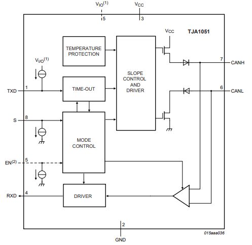
Ⅴ.Block diagram of TJA1051T/3/1J
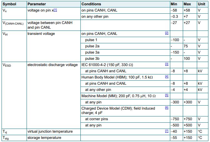
Ⅵ.Limiting values of TJA1051T/3/1J
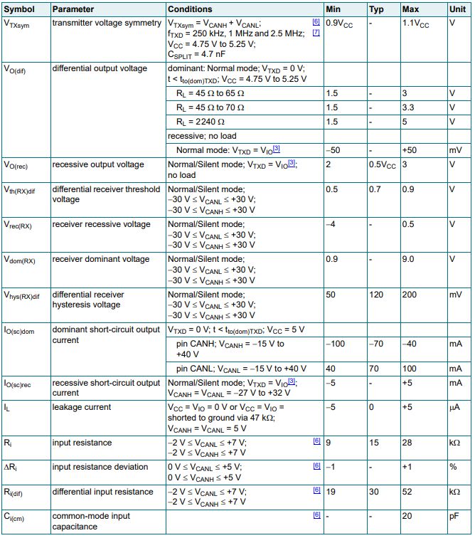
Ⅶ.Static characteristics of TJA1051T/3/1J
Ⅷ.How does TJA1051T/3/1J handle errors on the CAN bus?
1.Error counter: The transceiver usually maintains an error counter to record the number of errors on the bus. These counters typically include the receive error counter (REC) and the transmit error counter (TEC).
2.Error recovery: In the error passive state, some transceivers support automatic or manual error recovery mechanisms. This includes gradually decreasing the error counter through specific error recovery commands or waiting for a period of time to allow the transceiver to re-engage in normal communications.
3.Error reporting: When the error counter reaches a certain threshold, the transceiver may generate an error report. This report can be read by the microcontroller or system for appropriate error handling.
4.Error injection: Some transceivers support an error injection mechanism, allowing the test system to simulate error conditions to verify the system's behavior under error conditions.
5.Error passive state: When the error counter exceeds a predefined threshold, the transceiver enters the error passive state. In this state, the transceiver is still able to listen to the bus, but will not actively participate in communications to avoid further errors.
6.Overload protection: The transceiver has an overload protection mechanism to prevent communication failure due to bus overload.
Ⅸ.Replacement model of TJA1051T/3/1J
•TJA1051T/3/1J
•NCV7351D13R2G
•MCP2551
•SN65HVD1050
Frequently Asked Questions
1.What are the characteristics of TJA1051T/3/1J?
Some of the key features of the TJA1051T/3/1J are: overvoltage protection, overload protection, ESD protection and differential input and output.
2.How does TJA1051T/3/1J improve system reliability?
The fault-tolerant design in TJA1051T/3/1J can enhance the adaptability and robustness of the system in the event of a fault. For example, multiple backups and redundancy designs ensure that the system can still maintain normal operation even if some components fail.
3.How to deal with the heat dissipation problem of TJA1051T/3/1J?
Lay out the PCB board rationally, reduce unnecessary connections, and reduce circuit impedance to reduce heat generation during work. For the TJA1051T/3/1J package, you can choose a heat sink of appropriate size and fit it closely with the transceiver to take away the heat through natural heat dissipation or forced heat dissipation.